Light-emitting device having specific linear thermal expansion coefficient and gas barrier properties

a technology of thermal expansion coefficient and light-emitting device, which is applied in the direction of organic semiconductor device, discharge tube luminescnet screen, natural mineral layered product, etc., can solve the problems of poor luminance and light-emitting efficiency, high driving voltage of light emission, and use of flexible plastic substrates, so as to achieve excellent durability, light-emitting efficiency and luminance.

Inactive Publication Date: 2006-04-11
FUJIFILM CORP
View PDF16 Cites 6 Cited by
  • Summary
  • Abstract
  • Description
  • Claims
  • Application Information

AI Technical Summary

Benefits of technology

[0008]Accordingly, an object of the present invention is to provide a flexible, light-emitting device excellent in durability, light-emitting efficiency and luminance, and usable for plate-shaped light sources such as full-color display devices, backlights and illumination light sources, light source arrays of printers, etc.SUMMARY OF THE INVENTION
[0009]As a result of intense research in view of the above objects, the inventor has found that by utilizing a device structure (top emission-type), in which the emitted light is taken out from the opposite side to the substrate, and by using a flexible support substrate having as high gas barrier as that of glass, it is possible to obtain a flexible, light-emitting device having excellent luminance and durability. The present invention has been accomplished by this finding.

Problems solved by technology

The conventional organic, light-emitting devices are disadvantageous in that they require high driving voltage for light emission and are poor in luminance and light-emitting efficiency.
However, in any of light-emitting devices produced by the above dry method and those produced by the above wet method, the use of a flexible, plastic substrate provides extremely lower durability than the use of a glass substrate.
Accordingly, it has been considered difficult to provide commercially acceptable light-emitting devices by the wet method.
One of the reasons therefor is that a plastic substrate of PET, etc. has such large gas permeability and moisture permeability that the penetrating oxygen and moisture exert adverse effects on the performance of the light-emitting device.
When moisture exists in the light-emitting device, current flowing therein electrolyzes the moisture, generating a hydrogen gas and an oxygen gas and thus resulting in dark spots.
In addition, because extremely easily oxidizable metals are used for the cathode, they are reacted with moisture and oxygen, causing dark spots.
Another reason is that because there is difference in a linear thermal expansion coefficient by one order or more between the flexible, plastic substrate and the electrode materials (ITO and metals), electrode materials tend to peel off from the substrate due to a thermal hysteresis, resulting in cracking and decrease in the durability of the light-emitting device.
However, this is a sealing layer that cannot be used as a substrate.

Method used


Image

  • Light-emitting device having specific linear thermal expansion coefficient and gas barrier properties
  • Light-emitting device having specific linear thermal expansion coefficient and gas barrier properties

Examples


example 1

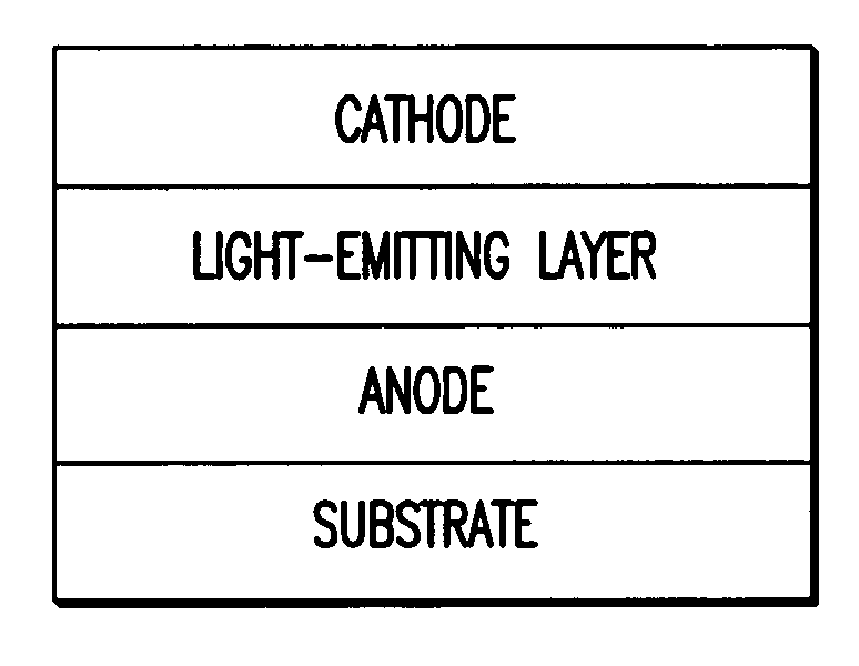
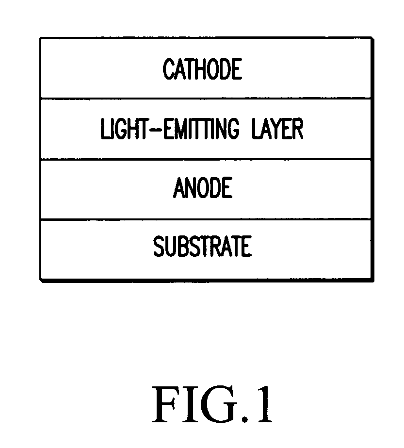
[0075]A 50-μm-thick polyimide film (UPILEX-50S, available from Ube Industries, Ltd.) was laminated onto both surfaces of a 5-cm-each aluminum foil (thickness: 30 μm) by an adhesive, to produce a support substrate. TMA measurement indicated that the support substrate had a linear thermal expansion coefficient of 10 ppm / ° C. The support substrate also had water permeability of 0.01 g / m2·day or less (MOCON method, 25° C., 90% RH), and oxygen permeability of 0.01 cc / m2·day·atm or less (MOCON method, 25° C., 0% RH).

[0076]A 250-nm-thick ITO layer with an indium / tin molar ratio of 95 / 5 was formed on this support substrate by a DC magnetron sputtering method to produce an anode. The anode had resistance of 7 Ω / square.

[0077]N,N′-dinaphthyl-N,N′-diphenylbenzidine was vapor-deposited on this anode in vacuum at a speed of 1 nm / second, to produce a 0.04-μm-thick, hole-transporting layer. Tris(2-phenylpyridine)iridium complex as an ortho-metallated complex, and 4,4′-N,N′-dicarbazole-biphenyl as a...

example 2

[0083]A light-emitting device was produced and evaluated in the same manner as in Example 1 except for using a copper foil (thickness: 50 μm) in place of the aluminum foil. The results are shown in Table 1. The TMA measurement indicated that the support substrate had a linear thermal expansion coefficient of 8 ppm / ° C. The support substrate also had water permeability of 0.01 g / m2·day or less (MOCON method, under the same conditions as in Example 1), and oxygen permeability of 0.01 cc / m2·day·atm or less (MOCON method, under the same conditions as in Example 1).

example 3

[0084]A light-emitting device was produced and evaluated in the same manner as in Example 1 except for using as an insulating layer a sputtered silicon oxide film (thickness: 30 nm) in place of the polyimide sheet. The results are shown in Table 1. The TMA measurement indicated that the support substrate had a linear thermal expansion coefficient of 5 ppm / ° C. The support substrate also had water permeability of 0.01 g / m2·day or less (MOCON method, under the same conditions as in Example 1), and oxygen permeability of 0.01 cc / m2·day·atm or less (MOCON method, under the same conditions as in Example 1).


PUM

PropertyMeasurementUnit
thicknessaaaaaaaaaa
thicknessaaaaaaaaaa
thicknessaaaaaaaaaa

Abstract

A light-emitting device including an anode, one or more organic compound layers containing at least a light-emitting layer, and a transparent cathode on a flexible support substrate having a linear thermal expansion coefficient of 20 ppm / ° C. or less, water permeability of 0.01 g / m2·day or less, and oxygen permeability of 0.01 cc / m2·day·atm or less. The flexible support substrate is constituted by a metal foil provided with an insulating layer on one or both surfaces thereof.

Description

FIELD OF THE INVENTION[0001]The present invention relates to a light-emitting device usable for plate-shaped light sources such as full-color display devices, backlights and illumination light sources, light source arrays of printers, etc., particularly to a flexible, light-emitting device excellent in light-emitting luminance and durability.BACKGROUND OF THE INVENTION[0002]Promising as inexpensive, solid-emission-type, large-emission-area, full-color display devices and writing light source arrays, the organic, light-emitting devices have been actively developed. The organic, light-emitting device generally comprises a couple of electrodes, and a light-emitting layer formed therebetween. When an electric field is applied to both electrodes, electrons are injected from the cathode, while holes are injected from the anode. When electrons and holes are recombined in the light-emitting layer, whereby an energy level is lowered from a conduction band to a valence band, energy is turned ...

Claims


Application Information

Patent Timeline
Patent Type & Authority Patents(United States)
IPC IPC(8): H05B33/04H01J1/62H01L51/50H01L51/52H05B33/02
CPCH01L51/52H01L51/5237H01L2251/5338H01L2251/5315H10K50/80H10K50/846H10K50/844H10K2102/3026H10K2102/311
Inventor MISHIMA, MASAYUKI
Owner FUJIFILM CORP
Why Eureka
Try Eureka