
Multimode semiconductor laser module, wavelength detector, wavelength stabilizer, and Raman amplifier

a multi-mode semiconductor laser module and amplifier technology, applied in semiconductor lasers, instruments, optical elements, etc., can solve the problem of inability to stabilize the output wavelength

Inactive Publication Date: 2006-04-11
SUMITOMO ELECTRIC IND LTD
View PDF42 Cites 2 Cited by
  • Summary
  • Abstract
  • Description
  • Claims
  • Application Information

AI Technical Summary

Benefits of technology

[0010]A multimode laser element, by contrast with a single-mode laser element, produces laser light over a relatively wide wavelength region. An optical filter transmits or reflects light over a certain wavelength region. Therefore, if the multimode light from the laser element enters the filter, the transmitted light from the filter will have a power corresponding to the degree of overlap between the oscillation wavelength region of the laser element and the transmission wavelength region of the filter. Also, the reflected light from the filter will have a power corresponding to the degree of overlap between the oscillation wavelength region of the laser element and the reflection wavelength region of the filter. Since the first light-receiving element receives the transmitted or reflected light from the filter, it generates an output signal reflecting change in the oscillation wavelength region of the laser element. Consequently, controlling the wavelength modifying means based on this output signal so that the oscillation wavelength region of the laser element approaches a desired region enables the oscillation wavelength region to be stabilized at the desired region.
[0011]The laser module may further comprise a light splitting device and a second light-receiving element. The light splitting device receives the multimode laser light from the first end surface of the laser element to produce two split beams. The second light-receiving element receives one of the split beams from the light splitting device. The optical filter receives the other split beam from the light splitting device. The light splitting device may regulate the ratio between the powers of the split beams provided to the optical filter and the second light-receiving element.
[0013]Since the light-receiving element receives the multimode light through the optical filter, it generates the output signal reflecting change in the oscillation wavelength region of the laser element. Therefore, modifying the oscillation wavelength region of the laser element based on the output signal toward a desired region enables the oscillation wavelength region to be stabilized at the desired region.
[0015]Since the first light-receiving element receives the multimode light through the optical filler, it generates an output signal reflecting change in the oscillation wavelength region of the laser element. Therefore, controlling the wavelength modifying means based on the output signal so that the oscillation wavelength region of the laser element approaches a desired region enables the oscillation wavelength region to be stabilized at the desired region.
[0018]Still another aspect of the invention provides a Raman amplifier. The Raman amplifier comprises an optical coupler, an optical transmission path for transmitting signal light, a laser module in accordance with the present invention, and a control circuit. Both the optical transmission path and the laser module are optically coupled with the optical coupler. The control circuit generates a control signal in response to the output signal of the first light-receiving element to control the wavelength modifying means. The wavelength modifying means modifies the oscillation wavelength region of the laser element according to the control signal. The optical coupler sends multimode light from the laser module to the optical transmission path. As a result, the multimode light excites the optical transmission path to Raman-amplify the signal light. Since the control circuit stabilizes the wavelength region of the multimode light from the laser module, the Raman amplifier performs Raman amplification reliably.

Problems solved by technology

Therefore, the output wavelength cannot be stabilized even when the etalon is used in the multimode LD module.

Method used


Image

  • Multimode semiconductor laser module, wavelength detector, wavelength stabilizer, and Raman amplifier
  • Multimode semiconductor laser module, wavelength detector, wavelength stabilizer, and Raman amplifier
  • Multimode semiconductor laser module, wavelength detector, wavelength stabilizer, and Raman amplifier

Examples


first embodiment

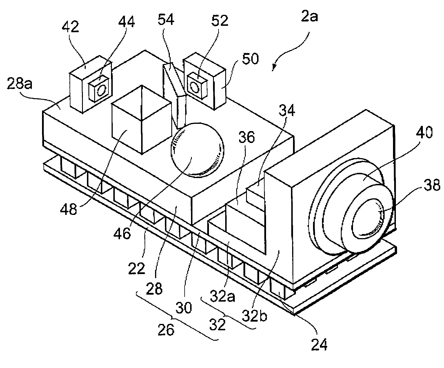
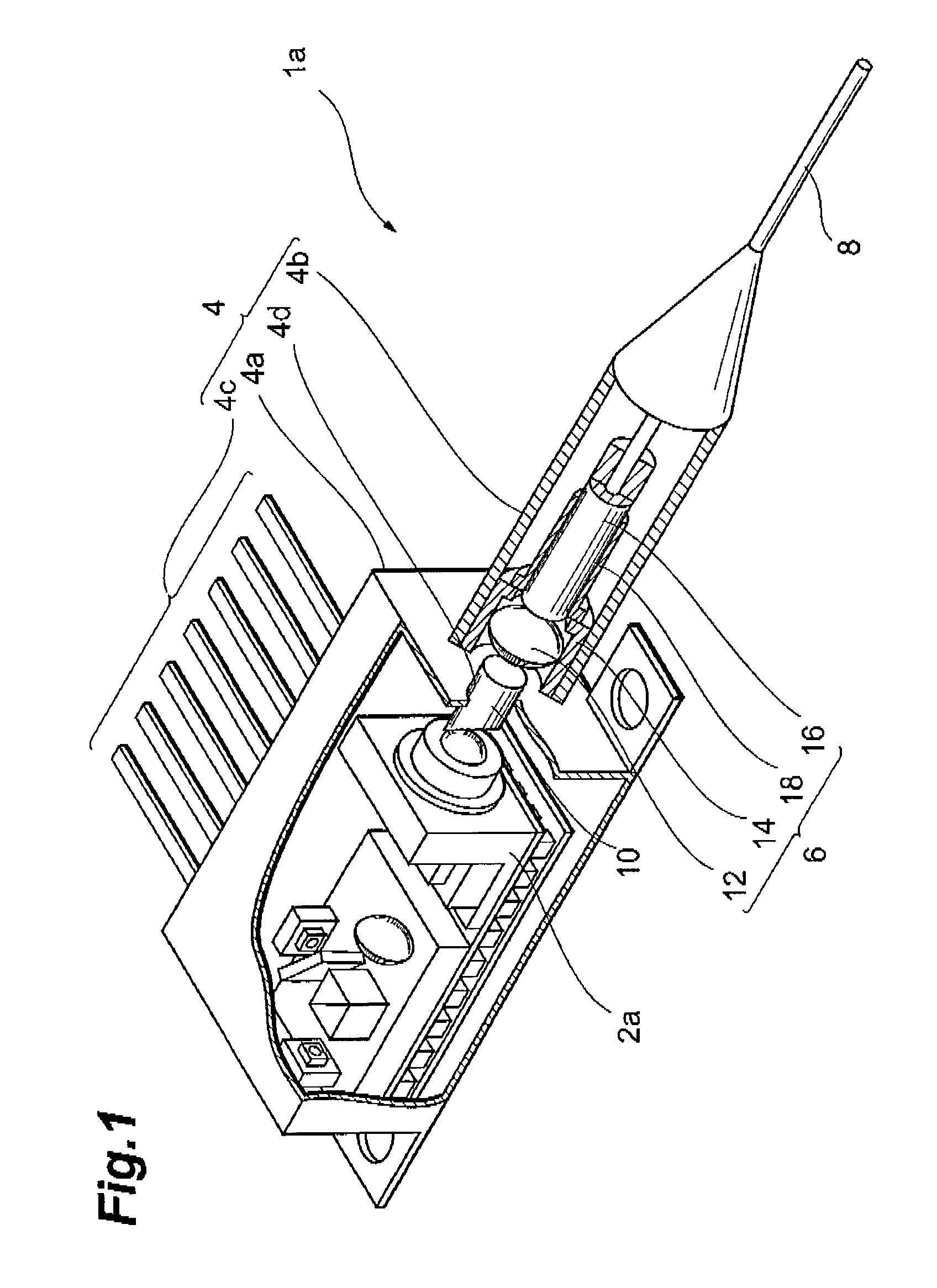
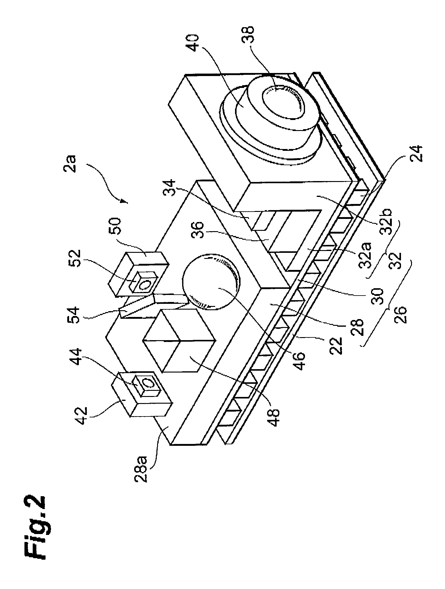
[0044]FIG. 1 is a partially cutaway perspective view illustrating the structure of a multimode semiconductor laser module 1a of this embodiment. The semiconductor laser module will be referred to as a LD module hereinbelow. The LD module 1a comprises a main part 2a, a housing 4, an optical coupling part 6, and an optical fiber 8.

[0045]The main part 2a provides multimode laser light whose wavelength is stabilized with some accuracy. The structure of the main part 2a will be described below in greater detail.

[0046]The housing 4 comprises an accommodation part 4a, an optical fiber supporting part 4b, a lead terminal 4c, and a light passing aperture 4d. The accommodation part 4a determines an arrangement space for accommodating the main part 2a. The optical fiber supporting part 4b is provided on the front wall of the accommodation part 4a. The fiber supporting part 4b holds the optical fiber 8 so that the optical fiber 8 is optically coupled with the main part 2a. The lead terminals 4c...

second embodiment

[0069]The second embodiment of the LD module in accordance with the present invention will now be described. The arrangement of the components in this embodiment is different from that in the first embodiment. In this embodiment, a light-receiving element for wavelength monitoring is disposed so as to receive light reflected by an optical filter. The other structural features are identical to those of the first embodiment.

[0070]FIG. 7 is a schematic view illustrating the arrangement of the components in the LD module of this embodiment. As shown in FIG. 7, the light-emitting element 52 receives reflected light G from the optical filter 54. Therefore, the output electric signal of the light-receiving element 52 is affected by the reflection characteristic of the filter 54. In other words, the reflection wavelength region of the filter 54 affects the output of the light-receiving element 52.

[0071]Regardless of whether the optical filter 54 is a long-wavelength-pass filer, a short-wave...

third embodiment

[0073]Referring to FIG. 8, the third embodiment of the LD module in accordance with the present invention will now be described. FIG. 8 is a perspective view illustrating another example of the main part of the LD module 1a. The LD module of this embodiment comprises a main part 2b shown in FIG. 8 instead of the main part 2a of the LD module 1a of the first embodiment. The other structural features are identical to those of the LD module 1a.

[0074]In the main part 2b, mounting members 60, 32 and 62 are arranged on the arrangement member 30 in the order of the description along an axis. The chip carrier 42 is disposed on the main surface 60a of the mounting member 60 to fix a light-receiving element 74 for power monitoring. The light-receiving element 44 faces the light-reflecting surface of the semiconductor laser element 34. Therefore, the light-receiving element 44 is optically coupled with the light-reflecting surface of the laser element 34 directly without interposing any optic...


PUM


Abstract

The present invention provides a multimode semiconductor laser module. The module comprises a multimode laser element 34, an optical filter 54, a light-receiving element 52 and a temperature regulator 24. Multimode light from the laser element 34 is transmitted through the filter 54 and then detected by the light-receiving element 52. The output of the light-receiving element 52 changes according to the degree of overlap between the oscillation wavelength spectrum of the laser element 34 and the transmission wavelength region of the filter 54. The temperature regulator 24 modifies the oscillation wavelength region toward the desired region in response to the output of the light-receiving element 52. As a result, the oscillation wavelength region is stabilized.

Description

BACKGROUND OF THE INVENTION[0001]1. Field of the Invention[0002]The present invention relates to a multimode semiconductor laser module, a wavelength detector, a wavelength stabilizer, and a Raman amplifier.[0003]2. Related Background Art[0004]There are semiconductor laser modules (abbreviated as LD modules hereinbelow) of two types: a single-mode LD module generating a single-mode laser beam and a multimode LD module generating a multimode laser beam.[0005]A single-mode LD module is used, for example, to generate signal light in a Wavelength Division Multiplexing (WDM) communication system. In WDM communication, signal light with a narrow line width is required. For this reason, the output wavelength of a single-mode LD module has to be controlled to an order of 10 pm. An optical element called etalon, which utilizes optical interference, is used to satisfy this requirement.[0006]Wavelength stabilization of a single-mode laser using an etalon is disclosed in Japanese Patent No. 291...

Claims


Application Information

Patent Timeline
IPC IPC(8): H01S3/13G02B5/28G02B6/42H01S5/022H01S5/0687H01S5/50
CPCH01S5/0687H01S5/02284H01S5/02216H01S5/02248H01S5/02325H01S5/02251
Inventor SASAKI, GORO
Owner SUMITOMO ELECTRIC IND LTD
Learn More