Apparatus and method for extending tuning range of electro-acoustic film resonators

a technology of electro-acoustic film resonators and apparatus, which is applied in the direction of resonance circuit tuning, oscillation generators, pulse techniques, etc., can solve the problems of low tuning accuracy, low frequency response, and low frequency response response, so as to minimize parasitic reactance, parallel resonance can be increased, and series resonance can be decreased

Inactive Publication Date: 2006-04-18
NAT SEMICON CORP
View PDF21 Cites 67 Cited by
  • Summary
  • Abstract
  • Description
  • Claims
  • Application Information

AI Technical Summary

Benefits of technology

[0007]The present invention overcomes the limitations described above by first increasing the spacing between the series resonance and parallel resonance of the film bulk acoustic wave resonator device using an external fixed inductance. The series resonance can be decreased (lowered) with an external series inductance and the parallel resonance can be increased (raised) with an external parallel inductance. Decreasing the series resonance is preferable in order to minimize parasitic reactances. A subsequently applied variable capacitor (varactor) is now able to pull either the series resonance or the parallel resonance over a greatly increased frequency range, thereby exceeding the initial spacing of the series and parallel resonances.
[0008]The increased range of frequency pulling is traded off for a lowered Q. However, a bank of multiple, switched resonator devices according to the principles of the present invention would achieve a high Q, as well as a wide tuning range. Advantageously, FBAR devices may be integrated on prefabricated CMOS wafers.

Problems solved by technology

As has been well reported, a number of technical obstacles have been encountered on the road to development of single chip transceivers.
One of these technical obstacles has been the tuning range, tuning accuracy, and phase noise of oscillator components in the transmitters and / or receivers.
Conventional varactor-tuned L / C circuits are less suitable because the resonant frequency and Q are defined by inaccurate and lossy inductor (L) and capacitor (C) components.
Conventional techniques for tuning either resonance with a series or parallel variable capacitor, respectively, are limited to the spacing of the two resonances.
The foregoing limits the usefulness of FBAR devices in single chip transceiver applications.

Method used


Image

  • Apparatus and method for extending tuning range of electro-acoustic film resonators
  • Apparatus and method for extending tuning range of electro-acoustic film resonators
  • Apparatus and method for extending tuning range of electro-acoustic film resonators

Examples


first embodiment

[0050]FIG. 4A illustrates conventional variable capacitor (varactor) tuning circuit 400 for changing the parallel resonance of film bulk acoustic-wave resonator (FBAR) 200 according to the prior art. Varactor, Cv, and its associated resistance, Rv, are shown in series with each other and form a parallel connection across the port of FBAR 200 (i.e., between Input 1 and Input 2).

[0051]FIG. 4B illustrates graph 401 of susceptance (jB) of conventional varactor tuning circuit 400 in FIG. 4A as a function of tuning frequency. Curve 410 represents the susceptance (jBFBAR) of FBAR 200. Curve 420 represents the susceptance (jBCVAR) of varactor Cv. Curve 430 represents the total susceptance (jBTotal). Even for an ideal varactor Cv that can be tuned from 0 pF to ∞ pF, the maximum tuning range of parallel resonance, fp, is from fPa to fSa (the letter “a” in the subscript means “acoustic”). The series resonance remains fixed at fSa. This range is too narrow to be of practical use for local oscil...

second embodiment

[0052]FIG. 5A illustrates conventional varactor tuning circuit 500 for changing the series resonance of thin film bulk acoustic-wave resonator (FBAR) 200 according to the prior art. Varactor, Cv, and its associated resistance, Rv, are shown in series with each other and form a series connection with Input 1 of the port of FBAR 200.

[0053]FIG. 5B illustrates graph 501 of reactance (jX) of conventional varactor tuning circuit 500 in FIG. 5A as a function of tuning frequenccy. Curve 510 represents the reactance (jXFBAR) of FBAR 200. Curve 520 represents the reactance (jXCVAR) of varactor Cv. Curve 530 represents the total reactance (jXTotal). Even for an ideal varactor Cv, that can be tuned from 0 pF to ∞ pF, the maximum tuning range of series resonance, fS, is from fSa to fPa. The parallel resonance remains fixed at fPa. Again, this range is too narrow to be of practical use for local oscillators.

[0054]FIG. 6A illustrates tuning circuit 600 for extending the parallel resonance tuning r...

third embodiment

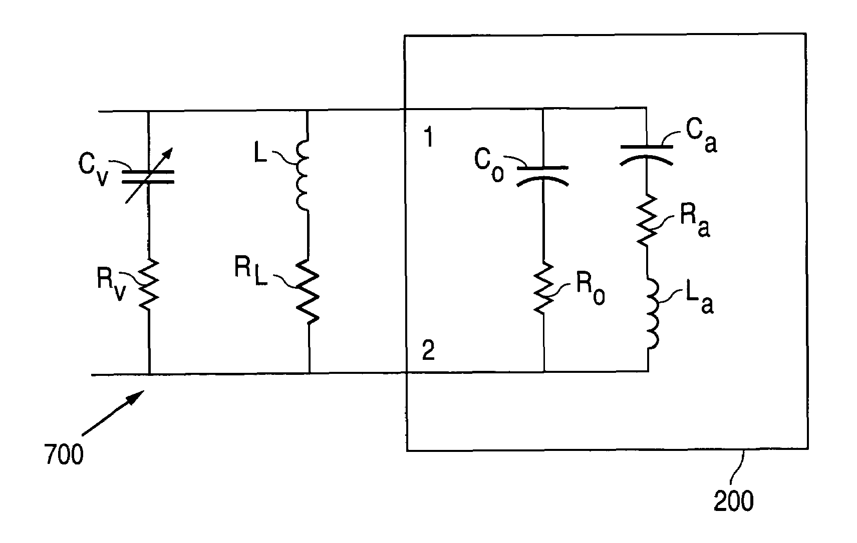
[0056]FIG. 7A illustrates tuning circuit 700 for extending the parallel resonance tuning range of film bulk acoustic-wave resonator (FBAR) 200 using external parallel inductance, L, according to the present invention. In FIG. 7A, inductor L and its associated resistance, RL, are shown in series with each other and are connected in parallel across Input 1 and Input 2 of FBAR 200. Similarly, varactor, Cv, and its associated resistance, Rv, are shown in series with each other and are connected in parallel across Input 1 and Input 2 of FBAR 200.


PUM


Abstract

A tuning circuit for adjusting an oscillation frequency of an oscillator circuit. The tuning circuit comprises a film bulk acoustic wave resonator (FBAR) having a series resonance frequency and a parallel resonance frequency, and an inductor coupled in series or parallel with the film bulk acoustic wave resonator. The series connection of the inductor and FBAR decreases the series resonance frequency. The parallel connection of the inductor and the FBAR increases the parallel resonance frequency. The tuning circuit further comprises a varactor coupled in series or parallel with the inductor and the FBAR combination. The varactor tunes the oscillation frequency over the increased tuning range.

Description

TECHNICAL FIELD OF THE INVENTION[0001]The present invention relates generally to high-frequency transceivers and, more particularly, to an apparatus and method for extending the tuning range of a local oscillator (LO) equipped with an electro-acoustic resonator for use in a high-frequency transceiver.BACKGROUND OF THE INVENTION[0002]Businesses and consumers use a wide array of high-frequency transmitters and receivers. These transmitter and receivers are used in unidirectional and bi-directional wireless devices (e.g., cell phones, wireless LAN cards, GPS devices), as well as unidirectional and bi-directional wireline devices (e.g., network interface cards). Increasingly, manufacturers of high-frequency communication devices are integrating most or all of the transmitter and receiver (generally, transceiver) circuitry onto a single integrated circuit die (i.e., chip) or at least onto a very small number of chips. As has been well reported, a number of technical obstacles have been e...

Claims


Application Information

Patent Timeline
Patent Type & Authority Patents(United States)
IPC IPC(8): H03H9/00H03B5/00
CPCH03J3/20H03B2201/0208H03J2200/36
Inventor SCHERER, DIETER
Owner NAT SEMICON CORP
Why Eureka
Try Eureka