OO control for injection molding machine

a technology of injection molding machine and control panel, which is applied in the direction of program control, electric programme control, instruments, etc., can solve the problems of increasing the complexity of the injection molding machine is much more complex than the one and the complexity of the injection molding machine is much more complex. , to achieve the effect of reducing errors

Inactive Publication Date: 2006-04-18
VAN DORN DEMAG CORP
View PDF7 Cites 24 Cited by
  • Summary
  • Abstract
  • Description
  • Claims
  • Application Information

AI Technical Summary

Benefits of technology

[0033]e) The machine control for an injection molding machine controls at least some of the machine components by OO program state machines having controller, observer and actuator classes or equivalents to i) assure state transitions, ii) assure state transitions in advance of the time actually required for

Problems solved by technology

In reality, the injection molding machine is much more complicated than what the operating sequence may indicate.
It can thus be readily seen from this general discussion that an injection molding machine is, in fact, a relatively complex system comprising many different hardware items that must operate in a synchronized manner.
Because the complexity of the injection molding machine has increased, the Boolean ladder logic programming requires more complex operations to be performed in the analog boards and in the control loops for the digital boards.
The problem confronting today's general purpose, injection molding machine manufacturer is not necessarily the responsiveness or functioning of the machine's controller, but the time and expense required to change the programmed routine when the customer specifies a particular machine from the family of machines offered to the market by the machine builder.
Because the machines are intensely price sensitive and the component changes materially change the machine price, the components are designed with

Method used


Image

  • OO control for injection molding machine
  • OO control for injection molding machine
  • OO control for injection molding machine

Examples


Embodiment Construction

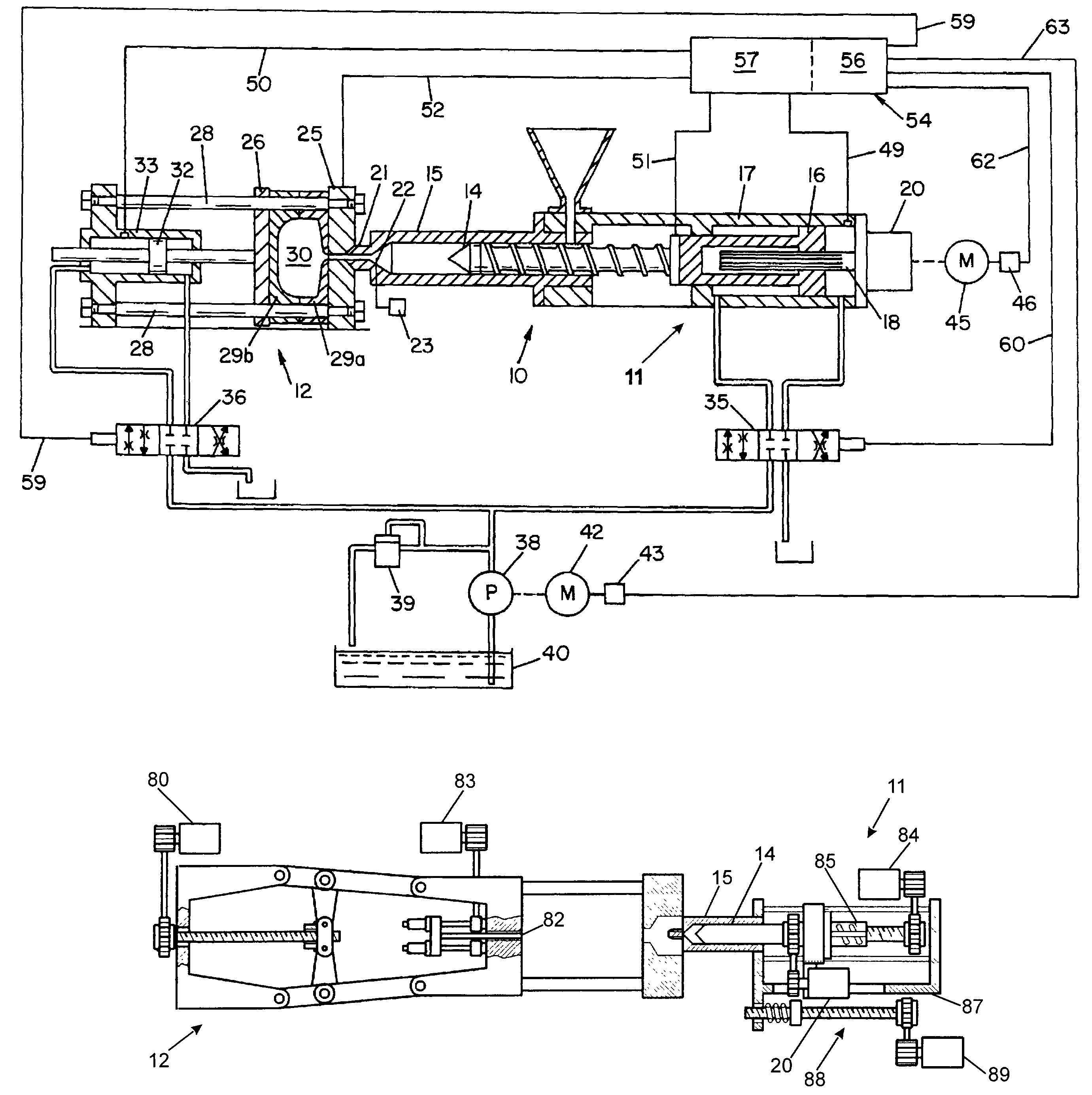
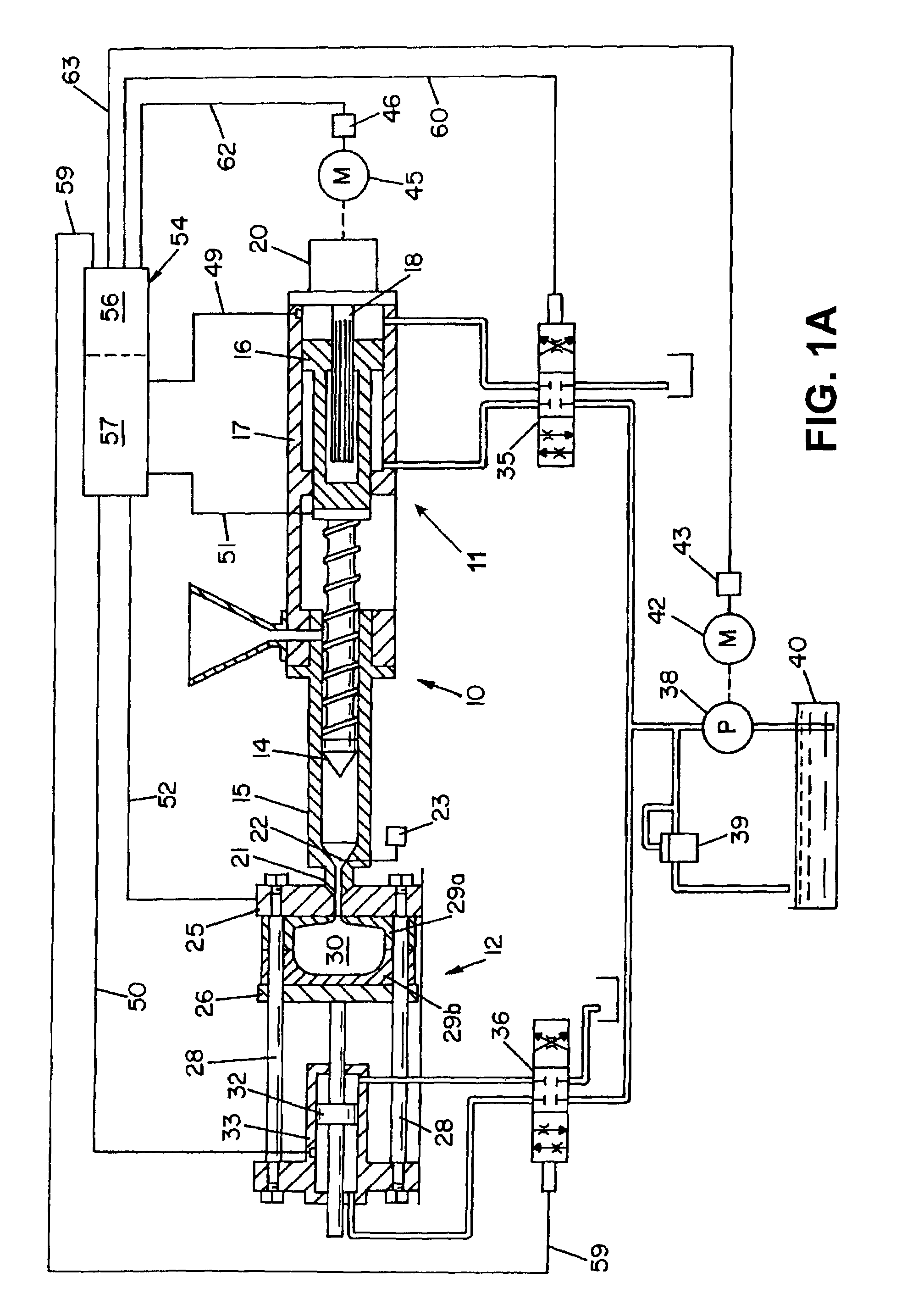
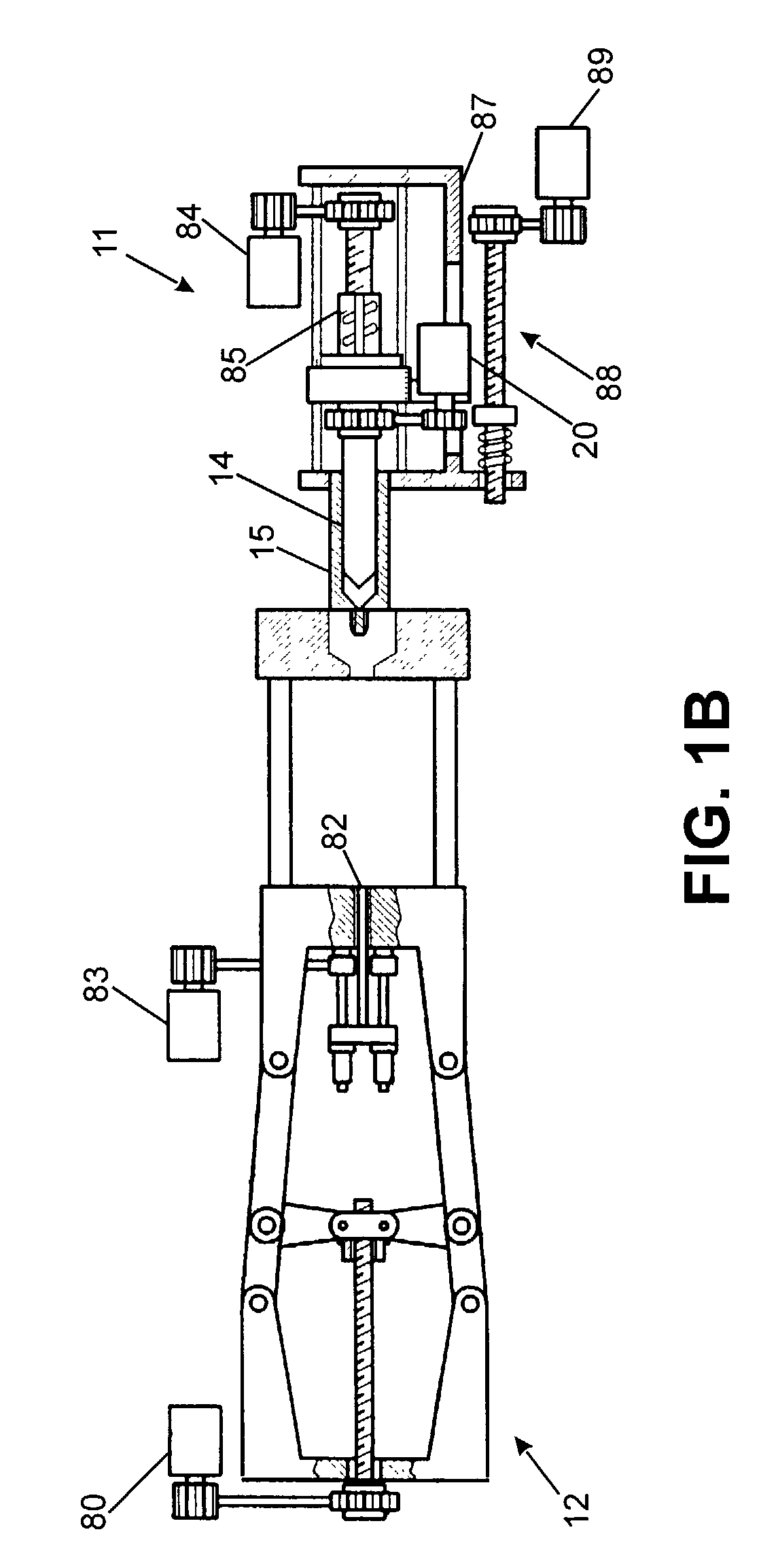
[0050]Referring now to the drawings where the showings are for the purpose of illustrating preferred embodiments of the invention only and not necessarily for limiting same there is shown in FIG. 1 a schematic representation of a plastic injection molding machine 10 of the hybrid type having an injection mechanism 11 and a clamp mechanism 12.

[0051]For terminology convenience and in order to avoid ambiguities, it should be understood that reference to “hydraulic drive” and “electric drive” and “drive systems” means the entire power transmission or drive train including the motor, its control, the coupling, etc. Reference to “motor drive” means the control used to govern the operation of the motor in response to a command signal issued by the machine's control system.

[0052]Injection mechanism 11 includes a screw 14 translatably and rotatably disposed within a tubular barrel 15. Translation of screw 14 within barrel 15 is achieved by a hydraulic actuator or hydraulic coupling shown to ...


PUM

PropertyMeasurementUnit
Timeaaaaaaaaaa
Structureaaaaaaaaaa
Sizeaaaaaaaaaa

Abstract

A plastic injection molding machine has an object oriented programmed routine to control the molding cycle of the machine. The programmed routine implements the inter-related molding cycle of clamp, inject, hold, eject and recover by development of classes corresponding to machine structure performing basic molding cycle steps. The basic classes use object oriented concepts of data encapsulation, inheritance, polymorphism, abstraction and the like that are linked together to produce objects during run time. The classes in turn include controller, observer and actuators classes. The controller class functions as a state machine. The observer class functions to determine the current state and the actuator class produces command signals controlling class related machine hardware. A modeling system is also disclosed for constructing the OO programmed routine for any injection molding machine using existing classes, principally by difference.

Description

CROSS REFERENCE TO PATENT APPLICATION(S) UNDER 35 USC §119, 120[0001]This application claims the benefit of Provisional Application No. 60 / 326,069 filed Sep. 29, 2001 entitled “OO Control for Injection Molding Machine.”[0002]This invention is also a continuation-in-part of non-provisional application Ser. No. 09 / 967,731 filed Sep. 29, 2001 now U.S. Pat. No. 6,682,669 entitled “Model Predictive Control Apparatus and Methods for Motion and / or Pressure Control of Injection Molding Machines” and a continuation-in-part of non-provisional patent application Ser. No. 09 / 968,357 filed Sep. 29, 2001, now U.S. Pat. No. 6,695,994 entitled “Melt Pressure Observer for Electric Injection Molding Machine.”[0003]This invention relates to injection molding machines and more particularly to an object-oriented control system for injection molding machines.[0004]This patent application incorporates by reference and makes a part hereof my non-provisional patent applications listed above. Specifically th...

Claims


Application Information

Patent Timeline
IPC IPC(8): G05B19/04B29C45/76
CPCB29C45/76B29C45/766G05B2219/45244B29C2945/76006B29C2945/76083B29C2945/7612B29C2945/76187B29C2945/76224B29C2945/76307B29C2945/76498B29C2945/76531B29C2945/76595B29C2945/76692B29C2945/76702B29C2945/76866B29C2945/76872B29C2945/76933G05B2219/34246
Inventor BULGRIN, THOMAS C.
Owner VAN DORN DEMAG CORP
Why Eureka
Try Eureka