Gas separating unit and method for manufacturing the same

a technology of gas separation unit and gas separation layer, which is applied in the direction of filtration separation, separation process, membrane, etc., can solve the problems of difficult formation of plating layer, inability to stably form heat treatment step with a definite thickness, and become a very cumbersome process, so as to increase the exposed area and increase the amount of permeable hydrogen gas

Inactive Publication Date: 2006-04-25
TOYO KOHAN CO LTD
View PDF27 Cites 14 Cited by
  • Summary
  • Abstract
  • Description
  • Claims
  • Application Information

AI Technical Summary

Benefits of technology

[0007]An object of the present invention is to provide a gas separating unit in which, in separating hydrogen gas, an effective area of a material capable of separating a hydrogen gas can be made larger and a method for manufacturing the same.
[0008]Furthermore, another object of the invention is to provide a method for manufacturing a gas separating unit that takes the handlability of a material capable of separating a hydrogen gas into consideration.
[0009]Still furthermore, still another object of the invention is to provide a gas separating unit that can increase an exposed area of a material capable of separating a hydrogen gas and can increase an amount of permeable hydrogen gas.

Problems solved by technology

However, there are problems in that it is difficult to form a plating layer excellent in the adherence directly on a metal support plate such as a stainless steel sheet and so on as mentioned above; and an alloy layer of palladium and nickel in the lastly applied heat treatment step may not be stably formed with a definite thickness.
Furthermore, there is another problem in that since in the plating, defects such as pinholes and so on are likely to occur, thin films of metal such as palladium and so on are formed with pores.
In particular, in the case of multi-layered plating being applied, since the conditions such as a plating bath composition, an electric current, a temperature and so on have to be strictly controlled; that is, it becomes a very cumbersome process.
Still furthermore, there is still another problem in that since an exposed area of a thin film of metal such as palladium and so on cannot be made larger, there is a limit in an amount of permeable gas.

Method used


Image

  • Gas separating unit and method for manufacturing the same
  • Gas separating unit and method for manufacturing the same
  • Gas separating unit and method for manufacturing the same

Examples


Embodiment Construction

[0020]In what follows, a hydrogen gas separating unit according to the present invention will be explained with reference to the drawings.

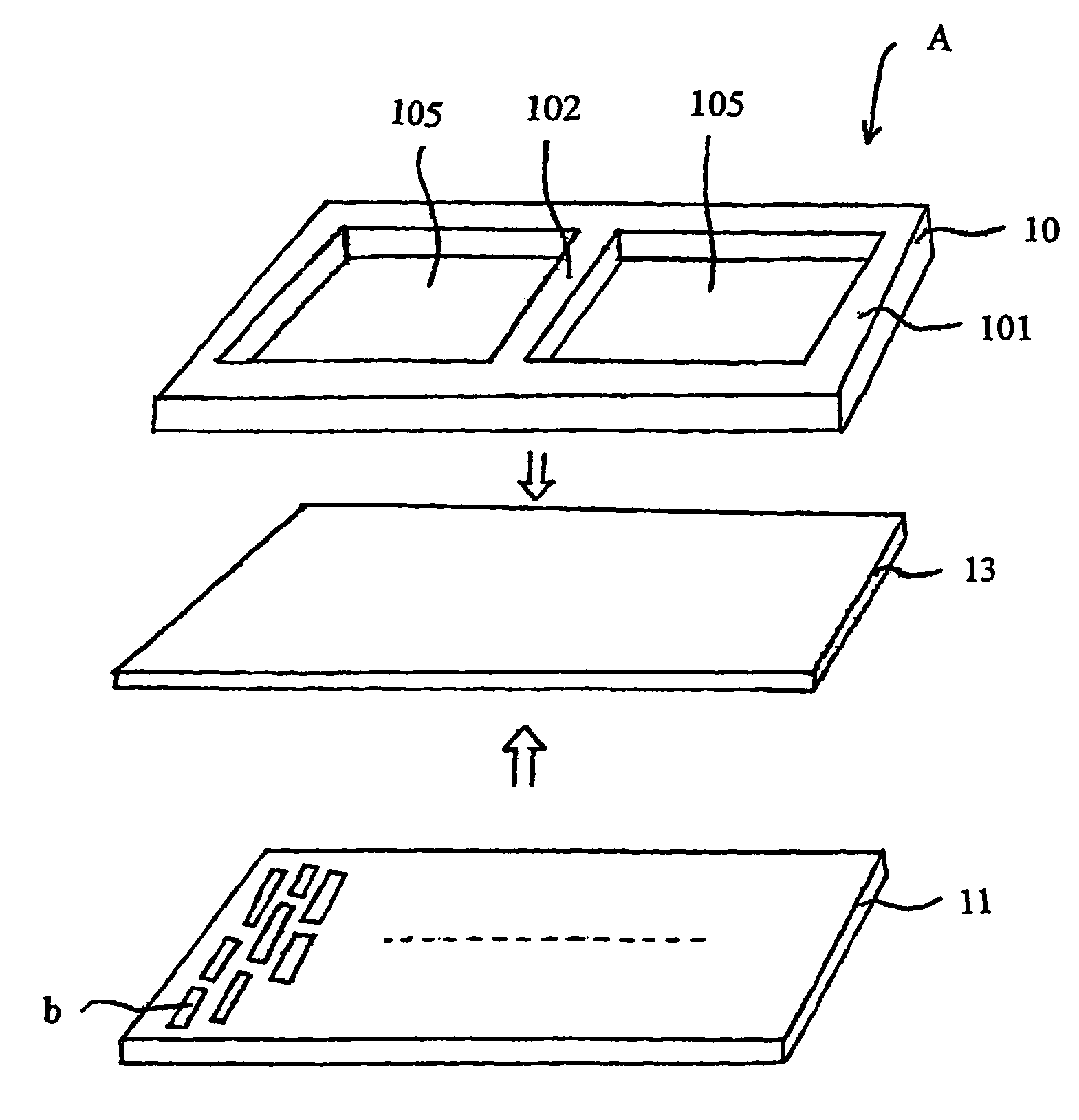
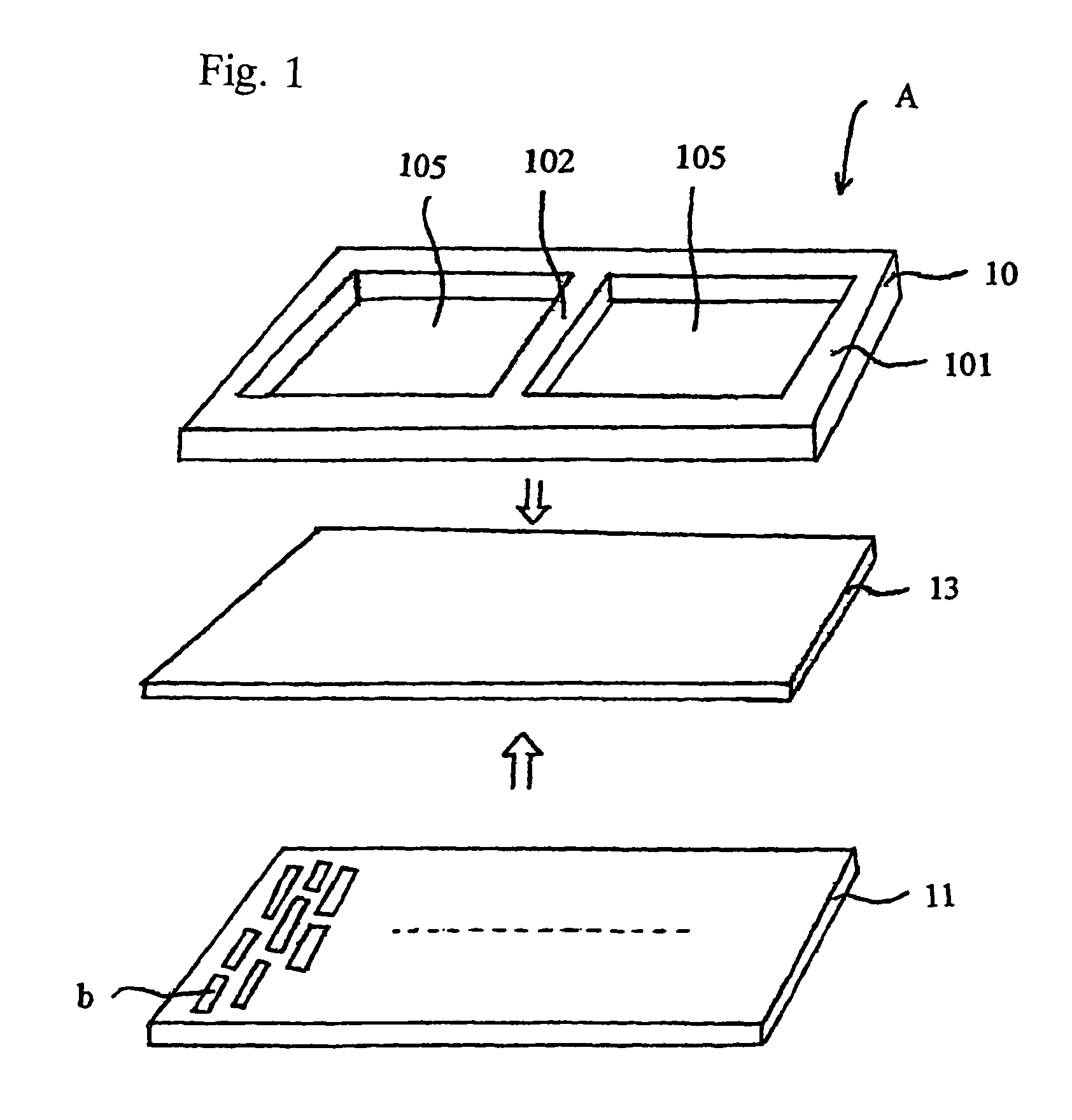
[0021]FIG. 1 is a perspective view in which in order to explain a structure of a hydrogen gas separating unit A, it is exploded in three layers of first, second and third layers.

[0022]In FIG. 1, in the hydrogen gas separating unit A, on one surface of a material 13 capable of separating a hydrogen gas (for instance, a palladium alloy foil; in the following explanation, the palladium alloy foil will be taken as an example) an extending frame 10 is laminated, and on the other surface thereof, a metal support 11 provided with a lot of holes is laminated.

[0023]As shown in FIG. 1, the extending frame 10 that is laminated on a top surface of the hydrogen gas separating unit A is a frame body having in a center portion thereof two openings 105 formed by etching and so on. As a shape of the openings 105, various shapes such as square, hexagon, circle, ell...


PUM

PropertyMeasurementUnit
thicknessaaaaaaaaaa
sizeaaaaaaaaaa
thicknessaaaaaaaaaa

Abstract

A method for manufacturing a gas separating unit which comprises laminating a metal plate on a material capable of separating a hydrogen gas (palladium alloy foil) by cladding, etching selectively a central portion of a cut clad plate (K) using an etching solution, to thereby expose an underlying palladium alloy foil layer, and providing a metal supporting plate on the other side of the palladium alloy foil layer. The method allows the manufacture of a gas separating unit having an enhanced effective area of a material capable of separating a hydrogen gas and is excellent in the handlability of a material capable of separating a hydrogen gas during manufacturing.

Description

TECHNICAL FIELD[0001]The present invention relates to a gas separating unit that separates a particular gas (for instance, hydrogen gas) in a mixed gas and a method for manufacturing the same.BACKGROUND ART[0002]So far, as a method of refining and recovering a hydrogen gas from a hydrogen-containing gas, there are methods such as a method in which impurities are separated and removed by use of a pressure swing absorption method (PSA method) that makes use of an absorbing agent and a method for separating hydrogen by use of an organic or inorganic hydrogen separating membrane. The method that uses a hydrogen separating membrane is gathering attention in view of energy saving, separation efficiency, simplicity of apparatus configuration, easiness in operation and so on.[0003]As the hydrogen separating membrane, membranes of organic polymers such as polyimide, polysulfone and so on; porous membranes of inorganic materials such as porous glass, porous ceramics and so on; and membranes o...

Claims


Application Information

Patent Timeline
Patent Type & Authority Patents(United States)
IPC IPC(8): C23C16/00B01D53/22B01D53/00B01D63/08B01D69/10B01D69/12B01D71/02C01B3/50
CPCB01D53/22B01D53/228B01D63/081B01D67/0072B01D69/10C01B3/505B01D71/022B01D2325/08C01B2203/0405Y10S55/05B01D2313/025B01D2325/04B01D71/02232B01D71/02231B01D69/108
Inventor SAIJO, KINJIOHSAWA, SHINJIOKAMOTO, HIROAKIYOSHIDA, KAZUOSEKI, TSUTOMU
Owner TOYO KOHAN CO LTD
Why Eureka
Try Eureka