Fabrication of a high fill ratio reflective spatial light modulator with hidden hinge

a spatial light modulator and high fill ratio technology, applied in the field of spatial light modulators, can solve the problems of limited gap between the mirror and the support wall, achieve high optical efficiency and performance, produce high-quality images reliably and cost-effectively, and facilitate manufacturing.

Inactive Publication Date: 2006-04-25
MIRADIA INC
View PDF53 Cites 70 Cited by
  • Summary
  • Abstract
  • Description
  • Claims
  • Application Information

AI Technical Summary

Benefits of technology

[0019]The net result is an easily manufacturable SLM that can achieve high optical efficiency and performance to produce high quality images reliably and cost-effectively.

Problems solved by technology

With no translational displacement, the gap between the mirrors and the support walls are limited only by the fabrication technology and process.

Method used


Image

  • Fabrication of a high fill ratio reflective spatial light modulator with hidden hinge
  • Fabrication of a high fill ratio reflective spatial light modulator with hidden hinge
  • Fabrication of a high fill ratio reflective spatial light modulator with hidden hinge

Examples


Embodiment Construction

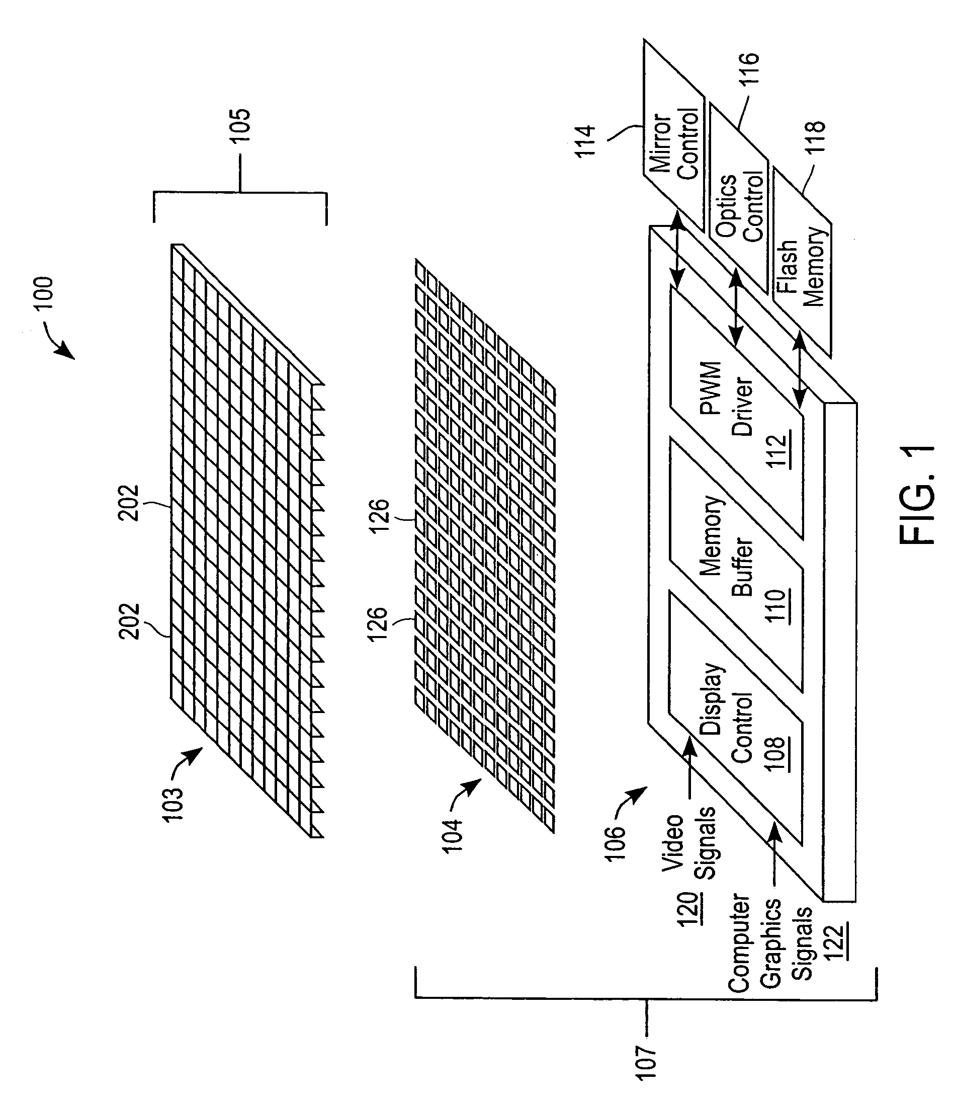
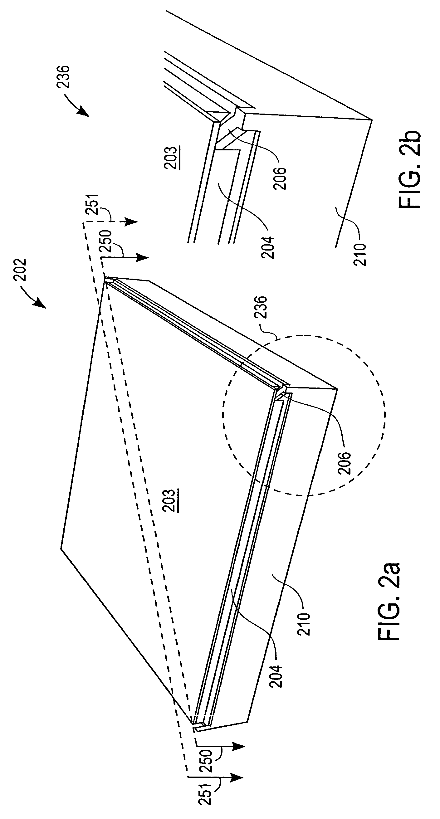
[0042]The reflective spatial light modulator (“SLM”) 100 has an array 103 of deflectable mirrors 202. Individual mirrors 202 can be selectively deflected by applying a voltage bias between that mirror 202 and a corresponding electrode 126. The deflection of each mirror 202 controls light reflected from a light source to a video display. Thus, controlling the deflection of a mirror 202 allows light striking that mirror 202 to be reflected in a selected direction, and thereby allows control of the appearance of a pixel in the video display.

Spatial Light Modulator Overview:

[0043]FIG. 1 is a schematic diagram that illustrates the general architecture of an SLM 100 according to one embodiment of the invention. The illustrated embodiment has three layers. The first layer is a mirror array 103 that has a plurality of deflectable micro mirrors 202. In one preferred embodiment, the micro mirror array 103 is fabricated from a first substrate 105 that, upon completion of fabrication, is a sing...


PUM

PropertyMeasurementUnit
thicknessaaaaaaaaaa
thicknessaaaaaaaaaa
thicknessaaaaaaaaaa

Abstract

Fabrication of a micro mirror array having a hidden hinge that is useful, for example, in a reflective spatial light modulator. In one embodiment, the micro mirror array is fabricated from a substrate that is a first substrate of a single crystal material. Cavities are formed in a first side of the first substrate. Separately, electrodes and addressing and control circuitry are fabricated on a first side of a second substrate. The first side of the first substrate is bonded to the first side of the second substrate. The sides are aligned so the electrodes on the second substrate are in proper relation with the mirror plates that will be formed on the first substrate and that the electrodes will control. The first substrate is thinned to a pre-determined, desired thickness, a hinge is etched, a sacrificial material is deposited, the upper surface of the first substrate is planarized, a reflective surface is deposited to cover the hinge, a mirror is released by etching and the sacrificial layer around the hinge is removed to release the hinge so the hinge can rotate about an axis in line with the hinge.

Description

CROSS-REFERENCE TO RELATED APPLICATION[0001]The present application is a continuation of application Ser. No. 10 / 610,967, “Fabrication of a High Fill Ratio Reflective Spatial Light Modulator with Hidden Hinge,” filed Jun. 30, 2003, now abandoned, which claims priority from provisional U.S. Patent Application Ser. No. 60 / 475,404, for “Hidden Hinge High Fill Ratio Reflective Spatial Light Modulator,” filed Jun. 2, 2003, the disclosure of which is incorporated by reference. This application also is a continuation-in-part of application Ser. No. 10 / 378,056, for “Reflective Spatial Light Modulator,” filed Feb. 27, 2003, now abandoned the disclosure of which is incorporated by reference, which claims the benefit of provisional U.S. Patent Application Ser. No. 60 / 390,389, for “Reflective Spatial Light Modulator,” filed Jun. 19, 2002. This application also is a continuation-in-part of application Ser. No. 10 / 378,041, for “Fabrication of a Reflective Spatial Light Modulator,” filed Feb. 27, ...

Claims


Application Information

Patent Timeline
Patent Type & Authority Patents(United States)
IPC IPC(8): H01L21/00G02B26/00G02B26/08
CPCG02B26/0841Y10S359/90
Inventor PAN, SHAOHER X.YANG, XIAO (CHARLES)
Owner MIRADIA INC
Why Eureka
Try Eureka