
Fiber optical gain equalizer

a gain equalizer and fiber technology, applied in the field of gain equalizers, can solve problems such as different profiles, and achieve the effects of low manufacturing cost, simple construction and operation, and simple application of control voltages

Inactive Publication Date: 2006-05-02
II VI DELAWARE INC
View PDF10 Cites 9 Cited by
  • Summary
  • Abstract
  • Description
  • Claims
  • Application Information

AI Technical Summary

Benefits of technology

The present invention provides a new fiber optical device that can control the wavelength profile in real time by adjusting the control voltages. This device is compact, polarization insensitive, simple in construction, and operational in a variety of applications. The invention also provides a new method for constructing a gain equalizer or wavelength selective filtering device using a stepped transparent substrate with phase shifting elements. The device can be used as a gain equalizer or wavelength selective filtering device by simply applying control voltages to the device. The invention also provides a new optical device that can process the spectral profile of an optical signal by controlling both the period of the Fourier components and the amplitude of the Fourier components. The device can be used as a gain equalizer or wavelength selective filtering device by simply adjusting the control voltages.

Problems solved by technology

Any inaccuracy in design or manufacturing procedure results in a profile different from that desired.

Method used


Image

  • Fiber optical gain equalizer
  • Fiber optical gain equalizer
  • Fiber optical gain equalizer

Examples


Embodiment Construction

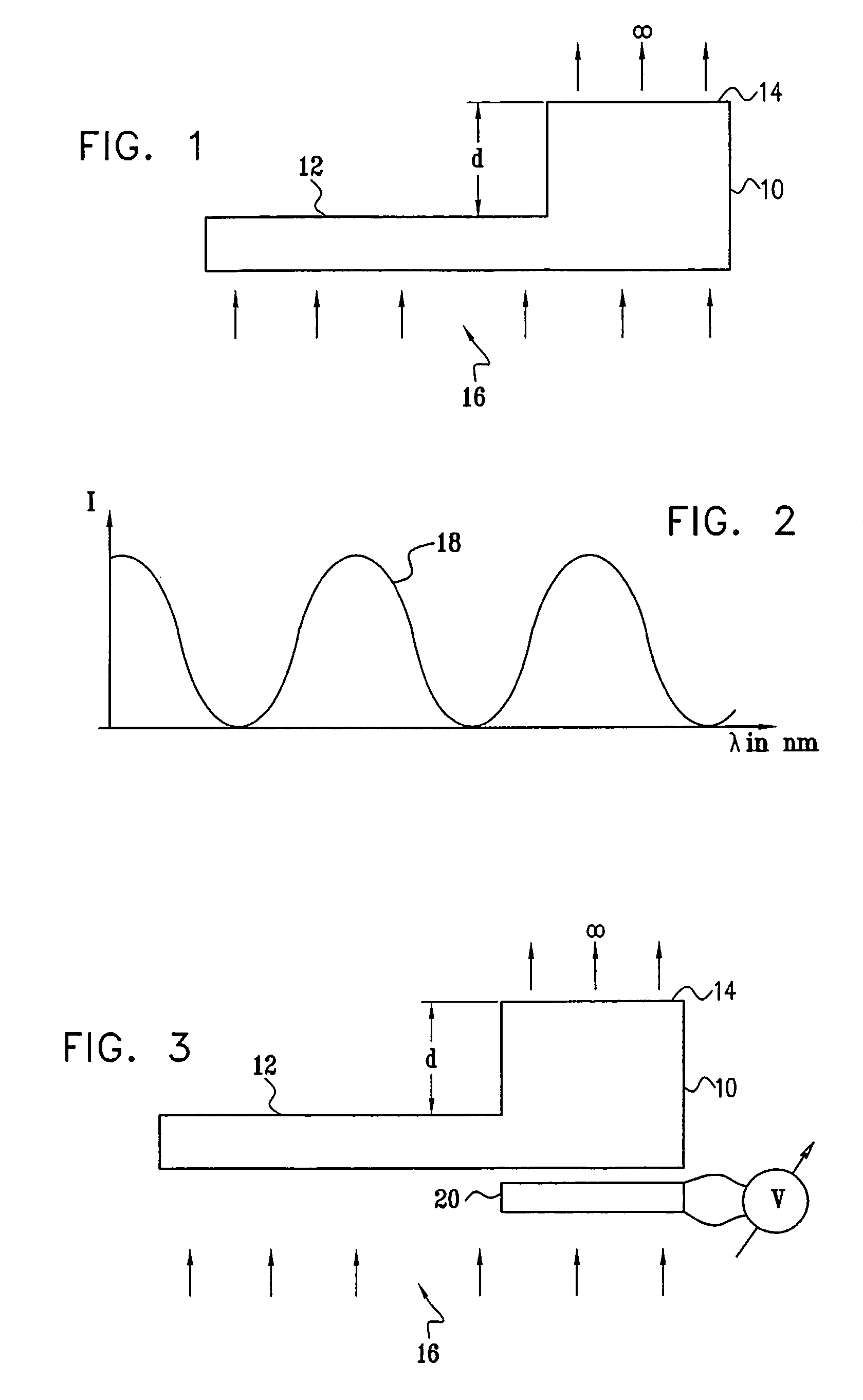
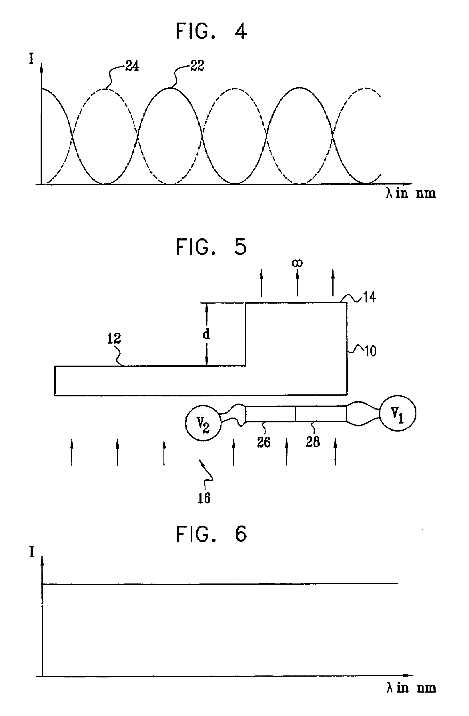
[0048]Reference is now made to FIG. 1, which illustrates schematically a stepped substrate 10, as is known in the prior art. The substrate, of total area A, is made of a transparent optical material of refractive index n. The substrate has a step 14 of area a, and of height d, projecting from the overall plane of its surface 12.

[0049]When a plane wave of light 16 of wavelength λ is projected through the substrate, then the light passing through the step undergoes a phase retardation θ, relative to that not traversing the step, given by:

θ=2π / λ·(n−1)d  (1)

[0050]The total transmitted intensity at optical infinity, of the light passing through the stepped substrate is then given by the expression:

I=|(A−a)+a exp(iθ)|2  (2)

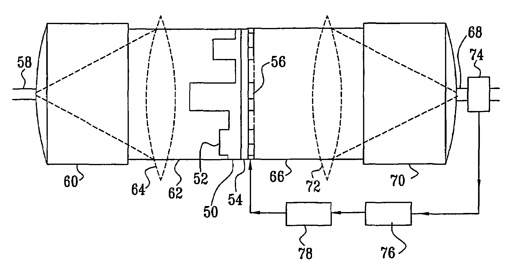
[0051]As is observed from incorporation of equation (1), the transmission is thus wavelength dependent. It is to be understood that the intensity obtained at optical infinity can be transformed to a near field plane by use of a converging lens, as will be illustrated in...


PUM

PropertyMeasurementUnit
phase shiftaaaaaaaaaa
phaseaaaaaaaaaa
wavelengthaaaaaaaaaa

Abstract

A fiber optical device, whose wavelength profile can be dynamically controlled in real time by the application of control voltages. The device can be used as a fiber optical gain equalizer or a wavelength selective filtering device which is compact, polarization insensitive, and of low manufacturing costs. The device comprises a stepped transparent substrate, through which the input beam is passed. Within the optical paths of the stepped regions of the substrate, electronically variable phase shifting elements are located, each operative to change the phase of the light passing through its associated step, and thus effectively adding tunability to the height of each step. Planar liquid crystal elements may be used as these elements. The elements may be pixelated, each pixel preferably affecting the phase of the light passing through a fraction of the area of the associated step, such that the interference so can be used to vary the transmission through that step. The pixels thus effectively add tunability to the area of each step. Electronic control of the height and area of each step enables the generation and dynamic control of complex transmission profiles.

Description

FIELD OF THE INVENTION[0001]The present invention relates to the field of gain equalizers using stepped substrate phase shifter techniques for implementing the wavelength selective function, especially for use in fiber optical applications.BACKGROUND OF THE INVENTION[0002]Gain equalizers are important components in fiber optical communication systems. One of the main functions of an optical gain equalizer is to bring all of the separate wavelength signals in a data transmission to the same amplitude, in order to optimize system spectral power budget. The functional requirements of an optical gain equalizer for use in such a system are that it should vary the intensity of the light transmitted as a function of the wavelength of the light, and without appreciably altering the spatial, temporal, or polarization distribution of the light beam.[0003]Many types of optical gain equalizers have been described in the prior art. In U.S. Pat. No. 6,144,488, to H. Okuno, for “Optically Amplifyi...

Claims


Application Information

Patent Timeline
Patent Type & Authority Patents(United States)
IPC IPC(8): G02F1/035G02F1/21H01S3/063H01S3/067H01S3/10
CPCG02F1/216H01S2301/04H01S3/06754
Inventor COREM, YOSSISUH, SEONGWOOCOHEN, GIL
Owner II VI DELAWARE INC
Learn More