Method of measuring motor constant for induction motor

a technology of induction motor and constant, which is applied in the direction of motor/generator/converter stopper, dynamo-electric gear control, motor/generator/converter stopper, etc., can solve the problem of large memory capacity of software, low efficiency, and long software processing time, so as to accurately control the induction motor and accurately tune the primary resistance

Inactive Publication Date: 2006-05-02
YASKAWA DENKI KK
View PDF6 Cites 17 Cited by
  • Summary
  • Abstract
  • Description
  • Claims
  • Application Information

AI Technical Summary

Benefits of technology

[0031]According to the present invention it is possible to accurately tune the primary resistance and secondary resistance, a leakage inductance and a mutual inductance or a no load current, which are required for accurately controlling an induction motor, even when a load is coupled to the induction motor.

Problems solved by technology

The method shown in Prior Art Example 1 is not suitable for automatic measurements by means of driving an inverter because it involves operations for fixing a rotor of an induction motor and releasing the fixation between a lock test and a no-load current test.
Also, in the no-load current test, the induction motor must be operated alone, so that if a load has been coupled thereto, an operation is required for once disconnecting the load to leave the motor alone, thus incurring a problem of a low efficiency.
Prior Art Example 2 needs complicated software because a single-phase AC current is applied and Fourier series expansion is utilized for the determination of a motor constant, thus requiring a long software processing time, and a large memory capacity for the software.

Method used


Image

  • Method of measuring motor constant for induction motor
  • Method of measuring motor constant for induction motor
  • Method of measuring motor constant for induction motor

Examples


first embodiment

[0060]A first embodiment will be described.

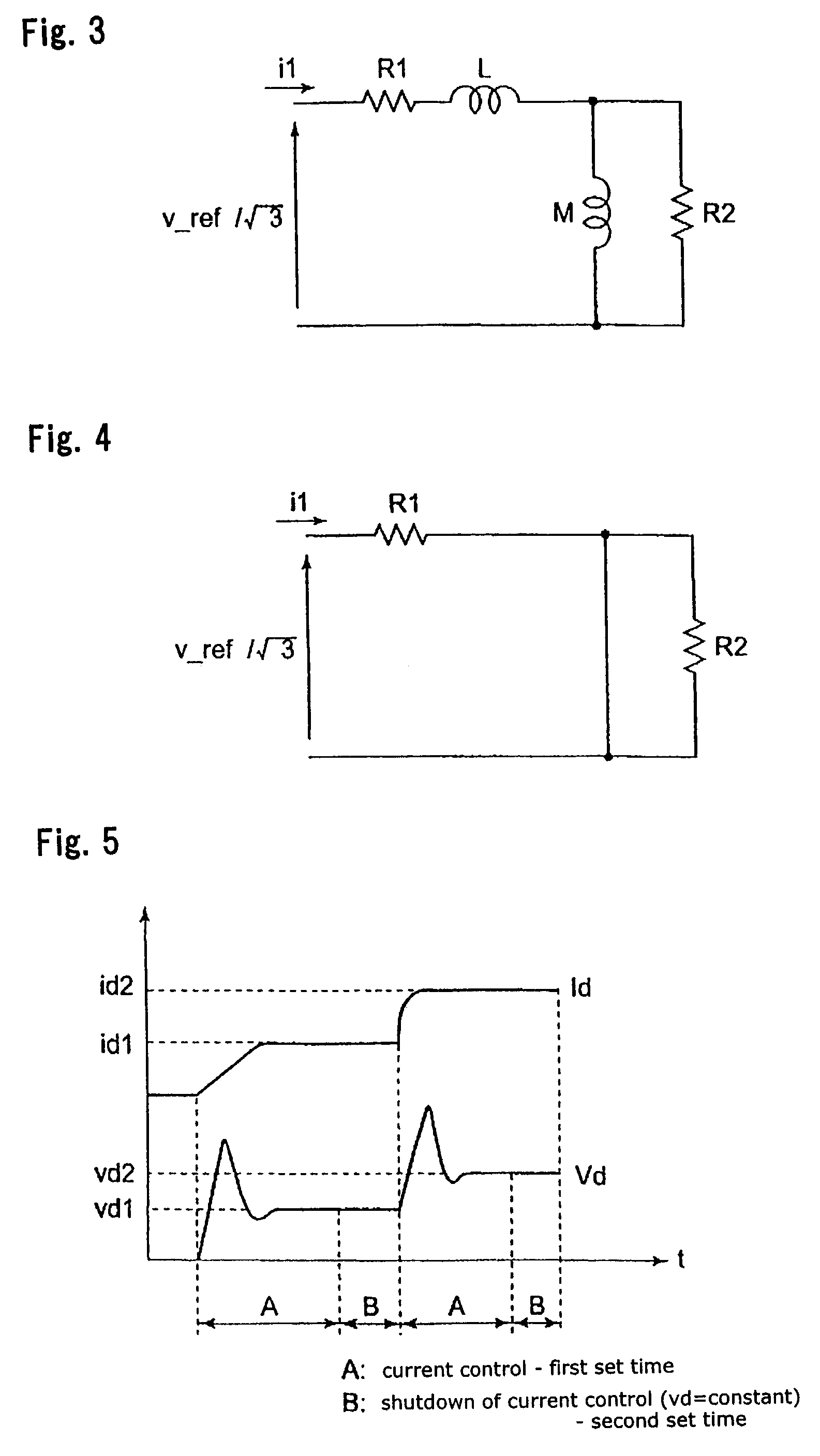
[0061]When a DC current is applied to induction motor 3, impedance ωM at mutual inductance M is zero, so that the equivalent circuit in FIG. 3 is changed as illustrated in FIG. 4. Therefore, primary resistance R1 is calculated in accordance with:

R1=(v_ref / √{square root over (3))} / I1

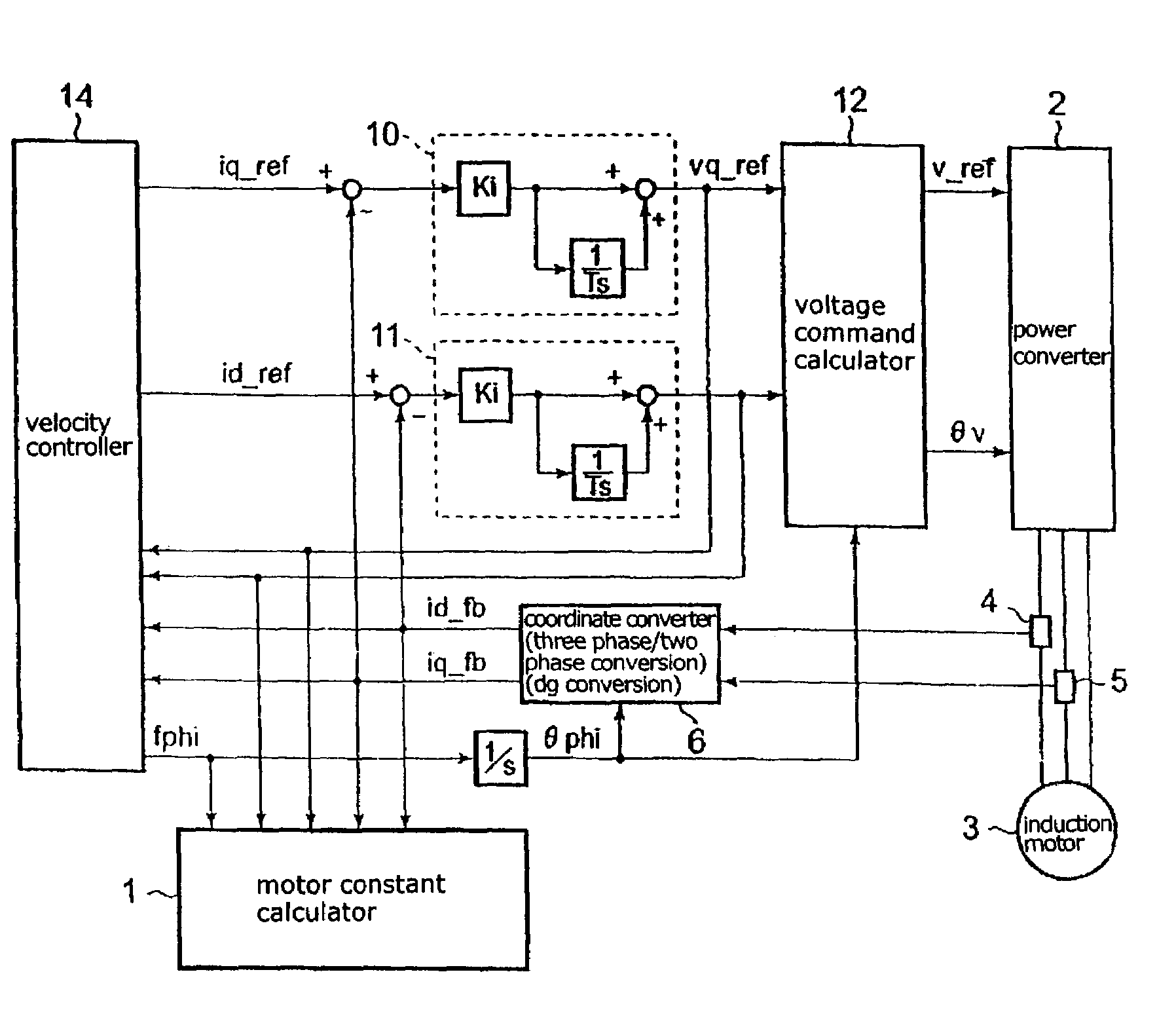
[0062]When setting as a line-to-line resistance, RL-L=2·R1 is handled as the line-to-line resistance. As tuning is started for the primary resistance, iq_ref and id_ref are applied as primary current command values arbitrarily set as a current command. As the current command is given, a voltage command is generated in accordance with the gain of proportional-plus-integral controllers 10, 11, and a three-phase AC voltage is delivered from power converter 2 and applied to motor 3 through which current I1 flows. Current I1 is detected by current detectors 4, 5, subjected to coordinate conversion and current processing, and resulting i_fb is applied to motor constant...

second embodiment

[0063]A second embodiment will be described.

[0064]The present embodiment is a modification of the first embodiment described above, wherein when proportional gain Ki of proportional-plus-integral controllers 10, 11 is set to zero, the q-axis and d-axis voltage commands at that time are substituted into auxiliary voltage command values vq_ref_c and vd_ref_c, respectively, and simultaneously, proportional gain Ki and integral gain (1 / T) of proportional-plus-integral controllers 10, 11, and the outputs of proportional-plus-integral controllers 10, 11 are set to zero, such that a resulting voltage command is applied. The remaining processing is the same as the first embodiment.

third embodiment

[0065]A third embodiment will be described.

[0066]While the current level is measured at two points in the first and second embodiments described above, the measurements are made at three points or more for improving the measurement accuracy in this embodiment. Describing for measurements at three points, when measurements are made at points 1, 2, 3, R1 is calculated in intervals between points 1 and 2, between points 2 and 3, and between points 1 and 3, respectively, or in arbitrary two of these intervals, as is the case in the first and second embodiments, and an average of calculated values is employed as R1 which should be determined. For measurements at four points or more, R1 may be similarly calculated in arbitrary intervals, such that an average of calculated values is used.


PUM


Abstract

A method of measuring a motor constant is provided in a vector control apparatus for an induction motor. A voltage output phase θv is set at a previously set arbitrary phase. Prior to applying a current, a current command is fed to operate the vector control apparatus with a proportional-plus-integral controller being set operative. After conduction for a predetermined time, the gain of the proportional-plus-integral controller is set to zero to maintain an integrated value constant and accordingly fix a voltage command value. In this state, a current command value and a detected current value are measured. This measurement is performed at two levels of current, and a primary resistance value (or a line-to-line resistance value) is derived from the slope.

Description

[0001]This application is the U.S. National Phase under 35 U.S.C. §371 of International Application PCT / JP01 / 05844, filed Jul. 5, 2001, which claims priority to Japanese Patent Application No. 2000-212896, filed Jul. 13, 2000. The International Application was published under PCT Article 21(2) in a language other than English.TECHNICAL FIELD[0002]The present invention relates to a method of measuring a motor constant for an induction motor.BACKGROUND ART[0003]There is software for controlling an inverter, which includes a method of determining a motor constant by conducting a winding resistance measurement, a lock test and a no-load test, as shown in JEC-37 (Prior Art Example 1). Also, JP-A-7-55899 discloses a method of tuning a constant of an induction motor while the induction motor remains inoperative (Prior Art Example 2). In this method, a single-phase AC current is supplied to an induction motor, and a detected d-axis current value or a detected q-axis current value is expande...

Claims


Application Information

Patent Timeline
Patent Type & Authority Patents(United States)
IPC IPC(8): H02P21/00G01R31/34H02P21/14H02P21/16H02P21/22H02P23/07H02P23/14H02P27/04
CPCG01R31/343G01R31/34
Inventor FUJII, SHUICHIIURA, HIDEAKIIDE, KOZOYUKIHIRA, YOSHIAKI
Owner YASKAWA DENKI KK
Why Eureka
Try Eureka