Method for detecting heat exchanger tube failures and their location when using input/loss performance monitoring of a recovery boiler

a heat exchanger tube and performance monitoring technology, applied in the direction of combustion measurement, fluid pressure measurement by mechanical elements, special data processing applications, etc., to achieve the effect of reducing the outage time required and improving the ability of system operators to predi

Inactive Publication Date: 2006-05-02
EXERGETIC SYST
View PDF12 Cites 19 Cited by
  • Summary
  • Abstract
  • Description
  • Claims
  • Application Information

AI Technical Summary

Benefits of technology

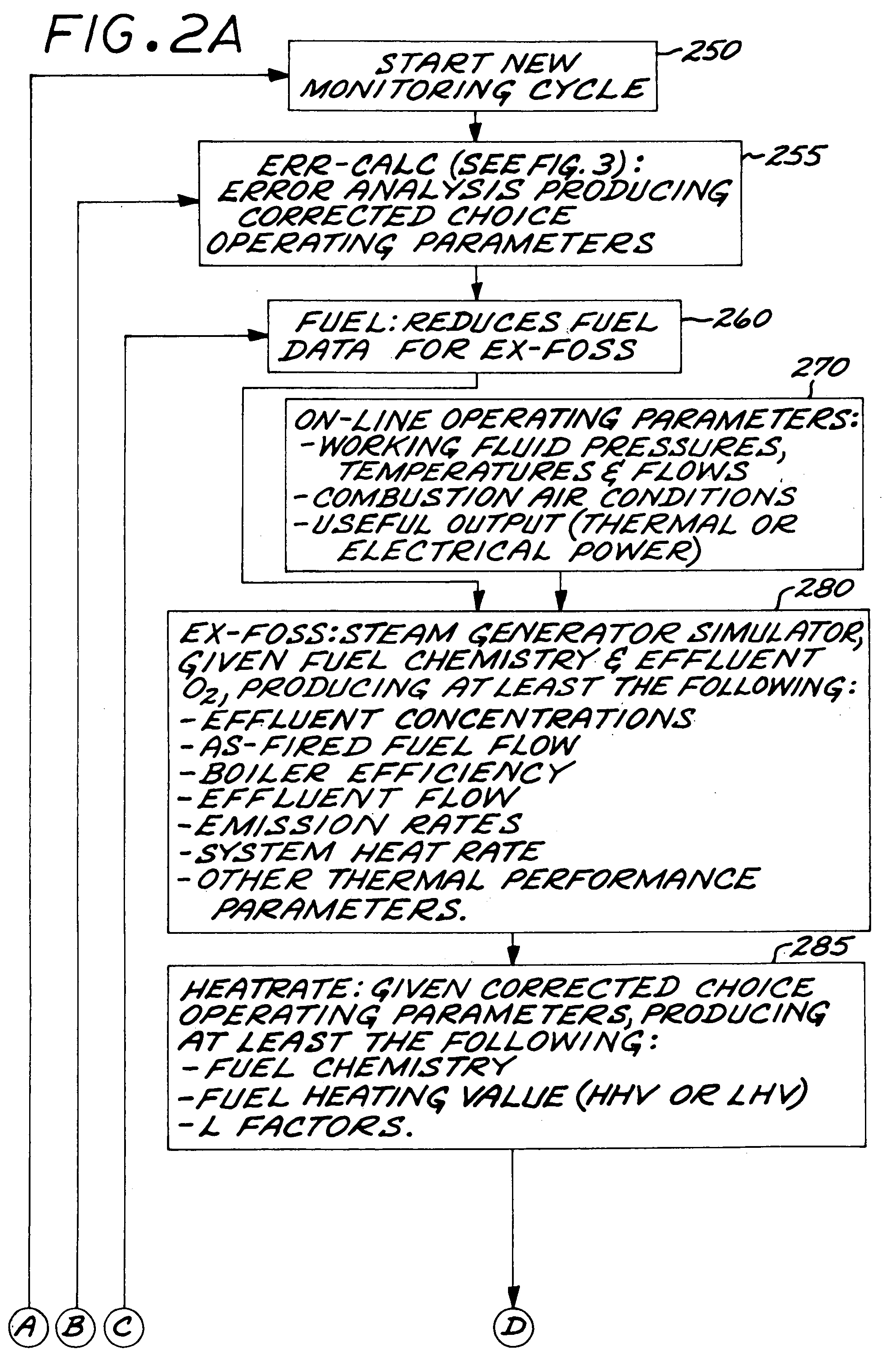
[0024]This invention adds to the technology associated with Input/Loss methods. Specifically The Input/Loss Method has been applied through computer software, installable on a personal computer termed a “Calculational Engine”, and has been demonstrated as being highly useful to the operators of fossil-fired systems. The Calculational Engine receives data from the system's data acquisition devices. The Calculational Engine's software consists of the EX-FOSS, FUEL and HEATRATE programs described in '994 and '429

Problems solved by technology

Conventional steam generators and recovery boilers having gas-to-working fluid heat exchangers, may be prone to tube leaks of their working fluid (typically water as liquid or steam).
These tube leaks represent a potential for serious physical damage to heat exchangers due to pipe whip (i.e., mechanical movement) and/or steam cutting of metal given high leakages flowing at critical velocities.
Given failure of a heat exchanger tube, such fluid will experience many times critical pressure ratio as it expands into the combustion gases; that is, mixing with the products of combustion at essentially atmospheric pressure.
When undetected, the damage from such tube failures may range from $2 to $10 million/leak forcing the system down for major repairs.
If detected early, tube failures may be repaired before catastrophic damage, such repairs lasting only several days and costing a fraction of the cost associated with late detection and catastrophic damage.
The problem of tube failures in recovery boilers, in addition to the conventional problems cited above, is when water comes in contact with the molten smelt (typically at over 1400 F, having a heavy concentration of sodium); explosion is likely and may occur within minutes after tube failure.
Recovery boiler explosions injure and kill people every year.
As common with conventional steam generators, tube failures in recovery boilers are typically caused by one the following general categories:Weld failure of heat exchanger tubes;Metallurgical damage caused by hydrogen absorption in the metal resulting in either embrittlement or the formation of non-protective magnetite;Caustic gouging caused by the prese

Method used


Image

  • Method for detecting heat exchanger tube failures and their location when using input/loss performance monitoring of a recovery boiler
  • Method for detecting heat exchanger tube failures and their location when using input/loss performance monitoring of a recovery boiler
  • Method for detecting heat exchanger tube failures and their location when using input/loss performance monitoring of a recovery boiler

Examples


Embodiment Construction

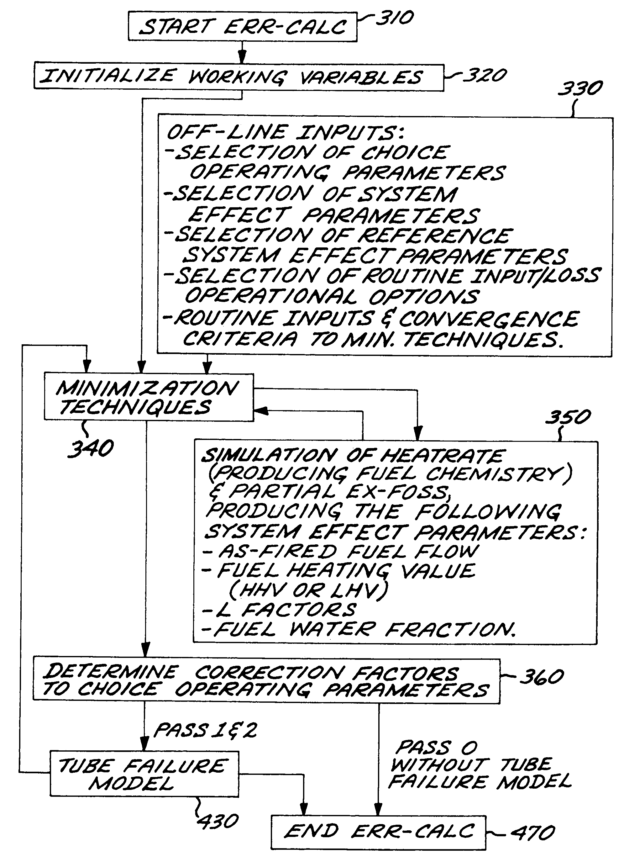
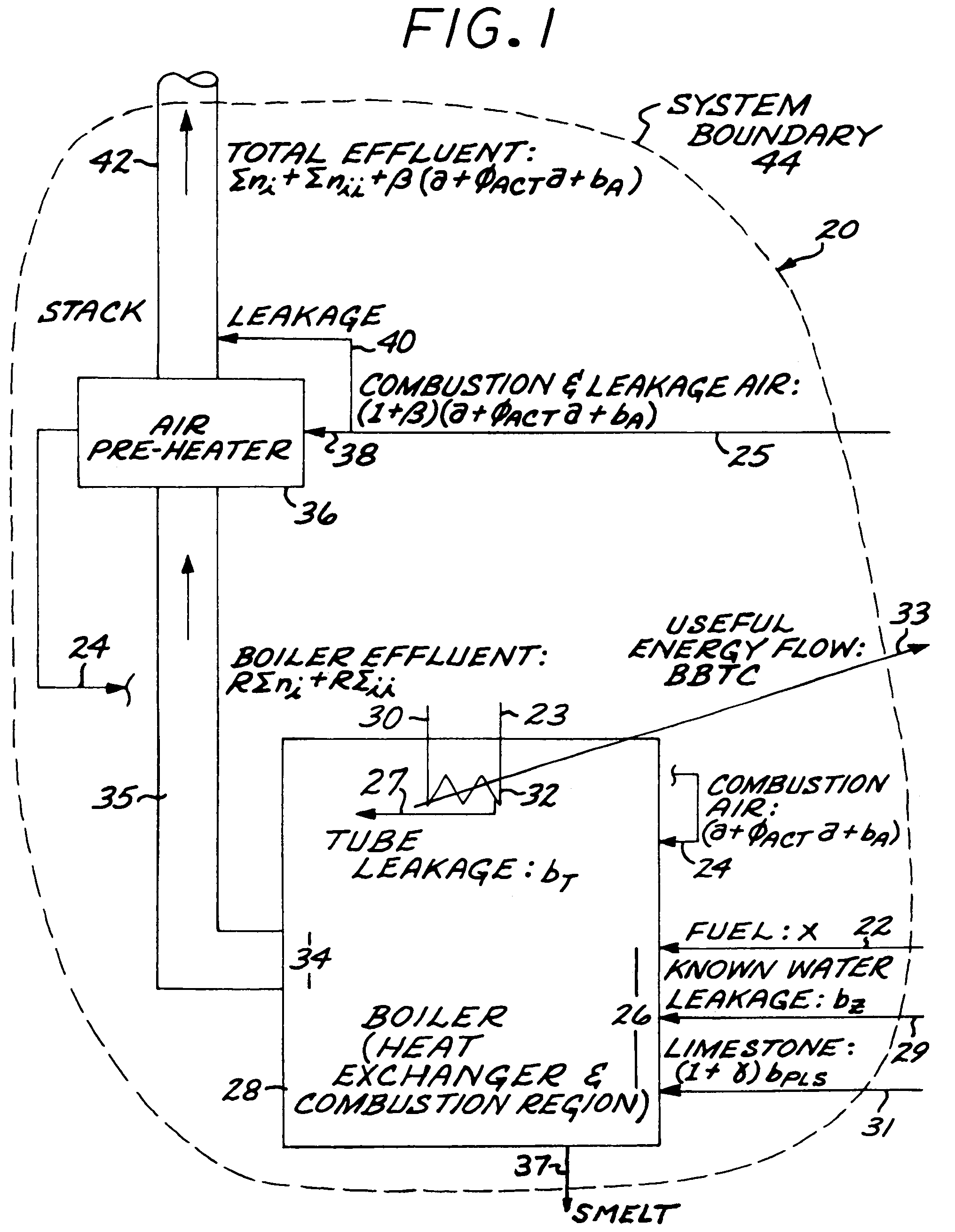
[0034]To assure an appropriate teaching of this invention, its description is divided by sub-sections. The first two present nomenclature, definitions of equation terms, typical units of measure, and meaning of terms used herein (such as Choice Operating Parameters and System Effect Parameters), encompassing the following seventeen paragraphs. The remaining sub-sections, representing the bulk of the teachings, are divided into four general groups:[0035]1) the first group presents system stoichiometrics applied to recovery boilers and the determination of fuel chemistry based on effluents, these teachings support all subsequent disclosures herein (encompassing the sub-section entitled “System Stoichiometrics”, employing equations numbered less than one-hundred);[0036]2) the next group presents the determination of boiler efficiency for a black liquor-fired boiler as it influences both tube failure flow rate and determining tube failure location (encompassing the sub-section entitled ...


PUM


Abstract

This invention relates to a recovery boiler as used by the pulp and paper industry burning black liquor, and, more particularly, to a method for rapid detection of tube failures and the location of the affect heat exchanger within the recovery boiler, without need for direct instrumentation, thereby preventing more serious equipment damage, preventing boiler explosion, preventing injury to operators and minimizing repair time on the affected heat exchanger. This method is applicable to Input/Loss methods of monitoring recovery boilers.

Description

[0001]This application is a Continuation-In-Part of U.S. patent application Ser. No. 10 / 268,466 filed Oct. 9, 2002, which issued on Nov. 18, 2003 as U.S. Pat. No. 6,651,035 for which priority is claimed and is incorporated herein by reference in its entirety. application Ser. No. 10 / 268,466 which, in turn, is a Continuation-In-Part of U.S. patent application Ser. No. 10 / 131,932 filed Apr. 24, 2002, which issued on Jun. 1, 2004 as U.S. Pat. No. 6,745,152 for which priority is claimed and is incorporated herein by reference in its entirety. application Ser. No. 10 / 131,932 which, in turn, is a Continuation-In-Part of U.S. patent application Ser. No. 09 / 273,711 filed Mar. 22, 1999, which issued on Feb. 18, 2003 as U.S. Pat. No. 6,522,994 and is incorporated herein by reference in its entirety; application Ser. No. 09 / 273,711 which, in turn, is a Continuation-In-Part of U.S. patent application Ser. No. 09 / 047,198 filed Mar. 24, 1998 now abandoned.[0002]application Ser. No. 10 / 131,932 is ...

Claims


Application Information

Patent Timeline
IPC IPC(8): G06F11/30F22B35/18F23N1/00F23N5/00G05B13/04G05B23/02
CPCF22B35/18F23N1/002F23N5/003F28F2265/00F23N2021/10F23N2023/40F23N2025/22F23N2021/08F23N2221/08F23N2221/10F23N2223/40F23N2225/22
Inventor LANG, FRED D.
Owner EXERGETIC SYST
Why Eureka
Try Eureka