

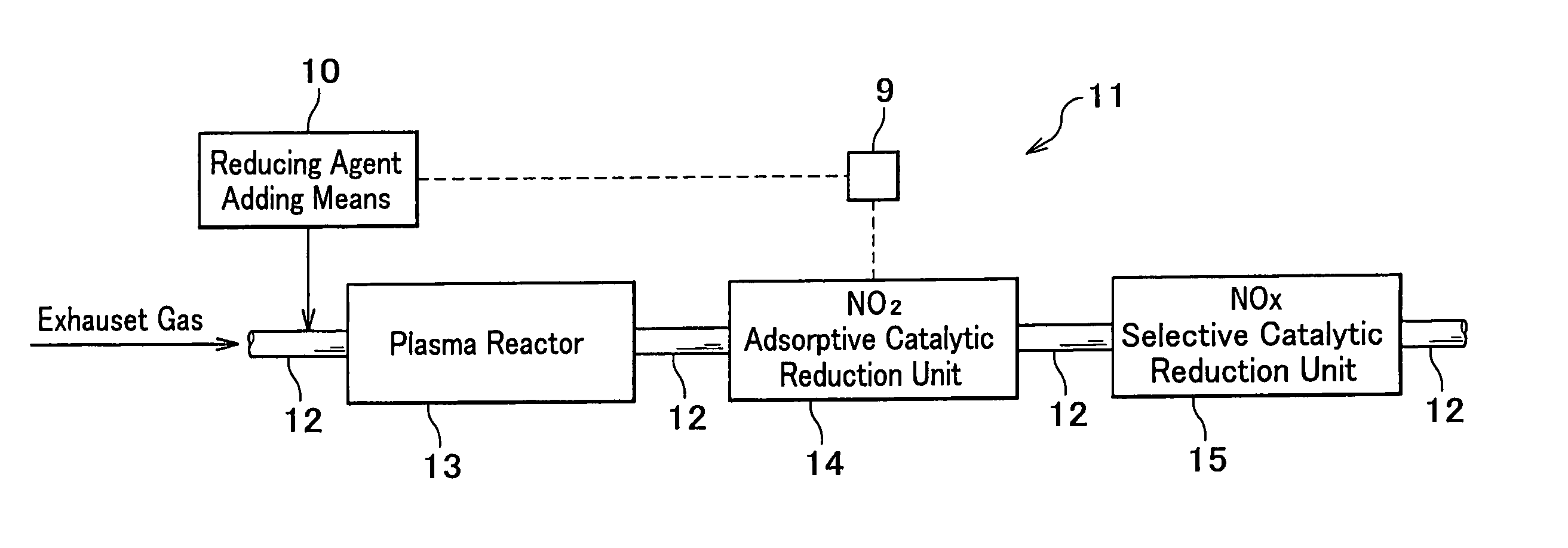
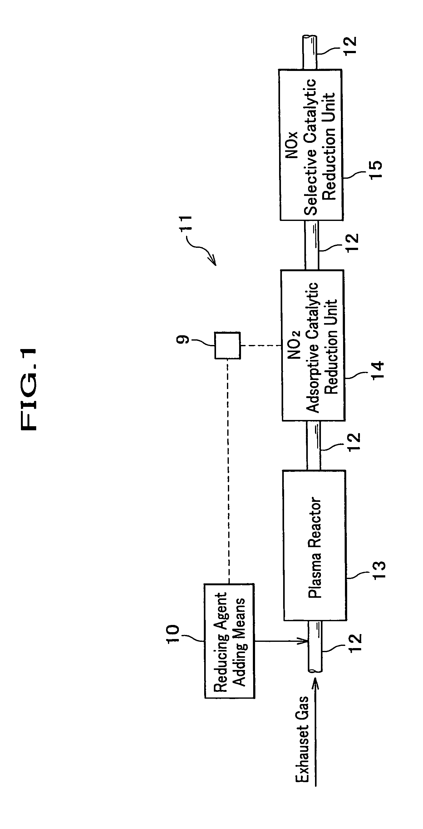
Exhaust gas purification system
a technology of exhaust gas and purification system, which is applied in the direction of physical/chemical process catalysts, metal/metal-oxide/metal-hydroxide catalysts, separation processes, etc., can solve the problems of high purification ratio, low /sub>purification ratio, and large fuel consumption loss, so as to achieve no2 selective reduction catalyst layer and no2 purification ratio heightened
- Summary
- Abstract
- Description
- Claims
- Application Information
AI Technical Summary
Benefits of technology
Problems solved by technology
Method used
Image

Examples
embodiment 1
a. Embodiment 1
(1) Manufacture of Catalyst Component A Used for NOx Adsorption Reduction Catalyst Unit
[0072]100 g of Na-USY type of zeolite, 133 g of kalium nitrate, and 1000 g of pure water were put in a separable flask, stirred for 14 hours while being heated up to 90 degrees Celsius, and filtrated. And after an obtained solid matter being washed with the pure water, it was dried at 150 degrees Celsius for two hours, and then baked at 400 degrees Celsius for 12 hours in a muffle furnace, thereby a K-ion exchange USY type of zeolite powder having been obtained. Meanwhile, an ion exchange ratio of kalium of the zeolite powder was 75%.
[0073]Next, 90 g of the zeolite powder, 50 g of an alumina binder (Al2O3 concentration: 20 mass percent), and 150 g of the pure water were put in a pot together with an alumina ball, and dryly pulverized for 12 hours, thereby a slurry catalyst having been adjusted.
[0074]In the obtained slurry catalyst was dipped a cordierite honeycomb support body of wh...
embodiment 2
b. Embodiment 2
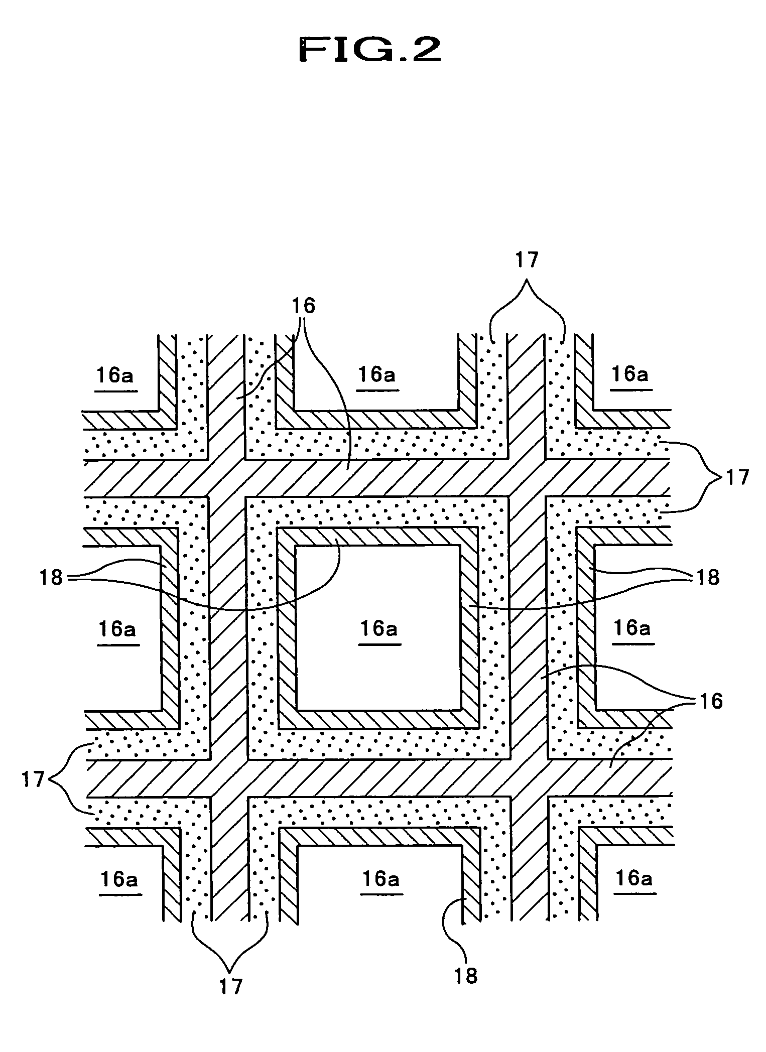
[0090]The exhaust gas purification system having been composed similarly to the embodiment 1 other than a wash-coat amount of the NO2 adsorptive catalyst layer 17 having been changed from 150 g / liter to 100 g / liter, the measurement test of the NO2 adsorption ratio was performed similarly to the embodiment 1. The result is shown in FIG. 9.
embodiment 3
c. Embodiment 3
[0091]The exhaust gas purification system having been composed similarly to the embodiment 1 other than a wash-coat amount of the NO2 adsorptive catalyst layer 17 having been changed from 150 g / liter to 20 g / liter, the measurement test of the NO2 adsorption ratio was performed similarly to the embodiment 1. The result is shown in FIG. 9.
PUM
| Property | Measurement | Unit |
|---|---|---|
| aperture diameter | aaaaa | aaaaa |
| concentration | aaaaa | aaaaa |
| thickness | aaaaa | aaaaa |
Abstract
Description
Claims
Application Information