
Anoxic reaction apparatus and process for obtaining an anoxic reaction therein

a reaction apparatus and reaction technology, applied in the field of anoxic reaction apparatus and process, can solve the problems of violent explosion, inability to completely guarantee the seal, and inability to undertake thermal decomposition operations using a continuous process, so as to reduce the cost and potential harm to the environment, save time, and reduce the effect of vacuum pump

Inactive Publication Date: 2006-05-23
FABSPEC
View PDF7 Cites 1 Cited by
  • Summary
  • Abstract
  • Description
  • Claims
  • Application Information

AI Technical Summary

Benefits of technology

[0044]The present application discloses a method and apparatus for purging oxygen from a sealed container interior and a purge substance used in such method. The method is exemplified herein in an improved batch process and apparatus for the thermal decomposition of hydrocarbon containing material in a sealed reactor interior. According to the present invention the improved batch process may comprise, 1) loading the hydrocarbon containing material into and sealing the reactor, 2) purging or expelling oxygen from said reactor, and 3) heating said reactor to a predetermined temperature so as to obtain decomposition products, the improvement residing in the purging step including loading the reactor with an oxyphilic solution prior to sealing and heating the interior of the sealed reactor to a predetermined temperature to induce the oxyphilic solution to drive oxygen out of the interior of the container through said gas evacuation component. The purge substance may be for example, an oxyphilic solution as described herein. When, for example, this process is used for the thermal decomposition of tires, gases and oil may be produced along with recyclable carbon black and steel residues which remain in the reactor at the end of the decomposition stage. The oxyphilic solution, when vaporized, creates a pressure rise that may help the vapor and air containing oxygen to be evacuated from the reactor, through evacuation means. As described herein, the oxyphilic solution may be reused from batch to batch and may comprise small chain hydrocarbons (hydrocarbons having 6 or 7 carbon atoms (C6 or C7)) in addition to water and alcohol. Surfactant may also be added as a coupling agent. Using the method of the present invention, material such as rubber, vinyl-polymers, styrene-polymers, ethylene-polymers, synthetic fibers, domestic waste, biomedical waste, animal waste and vegetation or any other type of hydrocarbon containing material and mixtures thereof may be efficiently processed.
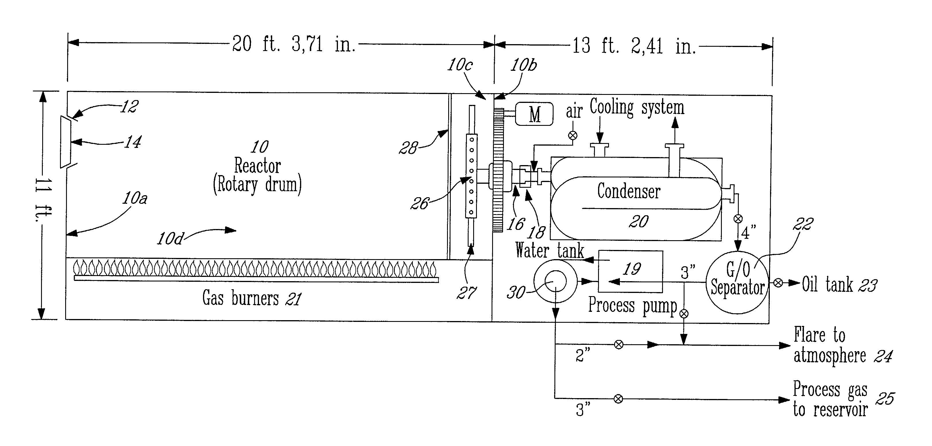
[0048]The gas and oxyphilic vapor are evacuated from the drum. The oxyphilic vapor may be condensed in a condenser and the gas may be partially flared and / or directed to atmosphere; the condensed vapor (including water and oxyphilic soultion) may be recuperated. The condensed vapor may comprise for example, water, alcohol and small chain hydrocarbons (e.g., hydrocarbons having 6 or 7 carbon atoms). One of the inventive aspects of the improved batch process described herein is that the condensed vapor may be recycled to generate the oxyphilic solution for the following batch process. This minimizes the cost and the potential harm to the environment associated with discharge. In order to generate the oxyphilic solution, the composition of the condensed vapor solution may be adjusted to a desired content with, for example, water, alcohol (water miscible alcohol; e.g., ethanol, isopropanol, n-butanol, isobutanol, and mixtures thereof) and nonionic surfactant, such as for example, Tween® 80 (which does not vaporize at 100° C.) in order to generate the oxyphilic solution.
[0049]A minor disadvantage of the present method, is that slightly more time is required to process a batch of fragmented rubber material compared to methods relying on vacuum pumps and devices. Indeed, while it took approximately 15 minutes to create an almost complete vacuum inside a drum of the above-mentioned dimensions (diameter of 8 feet, length of 20 feet), it takes approximately 20 minutes to perform a substance purge (to vaporize forty to fifty imperial gallons of solution) inside the drum. However, considering the economy in the vacuum pump, seals, and electricity and the potential risk that is avoided, the method of the present invention remains very advantageous over previously used methods.
[0053]As used herein a “oxygen-free environment” or a “anoxic environment” relates to environment (air contained in a container or reactor) containing negligible quantity of oxygen (less than 0.1% and not exceeding 1% (v / v) of the total air volume) that avoids risks associated with a thermal decomposition process as described herein.

Problems solved by technology

The main problem with such processes and apparatus is that seals are never totally reliable.
Considering the important consequences of outside air leakage into the reactor chamber, it is considered an unacceptable risk to undertake thermal decomposition operations by use of a continuous process.
The anoxic environment is essential since an oxygen (O2) leakage inside the apparatus (e.g., drum, reactor chamber) is likely to result in a violent explosion.
For this purpose, expensive vacuum pumps and seals are needed.
Thus, creating a vacuum inside a reactor chamber is an expensive step.

Method used


Image

  • Anoxic reaction apparatus and process for obtaining an anoxic reaction therein
  • Anoxic reaction apparatus and process for obtaining an anoxic reaction therein

Examples


example 1

[0075]The following result, illustrated in Table 2 is an example of the method disclosed herein, using the apparatus illustrated in FIG. 1. As a blank experiment, a volume of between 40 and 50 imperial gallons of freshly prepared oxyphilic solution was introduced in the drum (10). The drum was subsequently sealed. The temperature inside the drum (10) was raised and maintained at 100° C. Concentration of oxygen inside the drum was followed by a continuous analyzer using a chemical cell. Column 2 illustrates the volume of air (containing approximately 20.9% of O2 of the total air content (i.e., in percent by volume at 15° C. and 101.3 kPa) initially contained in the reactor that is gradually replaced by the volume occupied by the vaporized oxyphilic solution, as seen in column 3. As may be seen, from this example (Table 2), after 12.4 minutes, the volume of air containing O2 is negligible (0.147 cubic feet (ft3)). It may take less than 15 minutes to completely replace air with the vap...

example 2

[0077]The following is an example of an improved batch process based on the process described in U.S. Pat. No. 5,821,396, wherein an oxygen-free environment is generated using the method and oxyphilic solution described herein.

[0078]A drum (10) of 20 feet in length and 8 feet in diameter was used. Six tons (12 000 pounds) of used rubber tires which is equivalent to about 600 tires were first cut up in pieces of about 2″×2″ and loaded as tire cuttings into the stationary reactor drum with the reactor access door (14) at 12:00 o'clock. Forty-five (imperial) gallons of the oxyphilic solution containing water (56% (v / v) of total volume), alcohol (36% (v / v) of the total volume), small chain hydrocarbons (comprising a mixture of C6 and C7 hydrocarbons; 7% (v / v) of the total volume)) and polyethylene-(20)-sorbitan-monooleate (0.2 L, i.e., less than 1% (v / v) of the total volume) was added inside the reactor. The door was closed in an airtight manner. The drum was then driven at low speed of...


PUM


Abstract

The present application discloses a method and apparatus for purging oxygen from a sealed container interior and a purge substance used in such method. The method is exemplified herein in an improved batch process and apparatus for the thermal decomposition of hydrocarbon containing material in a sealed reactor interior. According to the present invention the improved batch process may comprise, 1) loading the hydrocarbon containing material into and sealing the reactor, 2) purging or expelling oxygen from said reactor, and 3) heating said reactor to a predetermined temperature so as to obtain decomposition products, the improvement residing in the purging step including loading the reactor with an oxyphilic solution prior to sealing and heating the interior of the sealed reactor to a predetermined temperature to induce the oxyphilic solution to drive oxygen out of the interior of the container through said gas evacuation component. The purge substance may be for example, an oxyphilic solution as described herein. Using the method of the present invention, material such as rubber, vinyl-polymers, styrene-polymers, ethylene-polymers, synthetic fibers, domestic waste, biomedical waste, animal waste and vegetation or any other type of hydrocarbon containing material and mixtures thereof may be efficiently processed.

Description

FIELD OF THE INVENTION[0001]The present invention relates to a new method for purging oxygen from a sealed container interior and a purge substance for accomplishing it. The present application more particularly discloses a process for the decomposition of hydrocarbon containing material exploiting the method described herein.BACKGROUND OF THE INVENTION[0002]The thermal decomposition of hydrocarbon containing material (i.e., pyrolysis) has been widely discussed. Both continuous and batch processes have been proposed and most of the processes described in the literature require an oxygen-free environment due to the high temperatures at which the process is performed.[0003]Prior art, such as U.S. Pat. No. 4,301,750 (Fio Rito; November, 1981), the entire content of which is incorporated herein by reference, discuss continuous processes performed under a substantially oxygen-free environment. The main problem with such processes and apparatus is that seals are never totally reliable. In...

Claims


Application Information

Patent Timeline
IPC IPC(8): C10B57/04B09B3/00B01J19/00C09C1/48C10B47/30C10B53/00C10B53/07C10G1/02C10G1/10
CPCC09C1/482C10B47/30C10B53/00C10G1/02C10G1/10C10B53/07Y10S585/951Y02E50/32Y02P20/143Y02E50/30C01P2006/80
Inventor BOUZIANE, RICHARDTREMBLAY, GILLES
Owner FABSPEC
Learn More