Volume adjustment device, digital amplifier, and digital signal reproducing device

a digital amplifier and volume adjustment technology, applied in the direction of dc amplifiers with modulator-demodulator, amplifiers with semiconductor devices/discharge tubes, amplification control details, etc., can solve the problems of inability to obtain sufficient servo gain, and drop in the maximum output (maximum volume) of amplifiers, so as to suppress deterioration of audio performance, reduce power consumption of amplification means, and output the power source voltag

Inactive Publication Date: 2006-05-23
SHARP KK
View PDF13 Cites 16 Cited by
  • Summary
  • Abstract
  • Description
  • Claims
  • Application Information

AI Technical Summary

Benefits of technology

[0023]Thus, it is possible to minimize the driving voltage without influencing a switching operation of the switching element, so that it is possible to reduce the power consumption of the driving circuit when an amplitude of an output is small.
[0032]The digital amplifier of the present invention includes: any one of the volume control devices arranged in the foregoing manner; 1-bit conversion means for converting the audio signal into a 1-bit signal; and the amplification means. Thus, it is possible to provide a digital amplifier which consumes less power and has higher audio performance.

Problems solved by technology

However, the arrangements of FIG. 8 and FIG. 9 have the following problems in terms of the power consumption.
However, this raises the following problem: drop of the power source voltage causes the output level to drop, so that a maximum output (maximum volume) also drops.
Thus, a sufficient servo gain cannot be obtained in case of a low voltage, so that a voltage which has not been sufficiently servoed by the servo circuit is supplied to the switching amplification means.
As a result, this raises the following deterioration of an audio performance: a distortion scale factor increases; S / N drops; and remaining noise increases.
However, power consumption in other circuits is the same as power consumption in the case where the volume is high.

Method used


Image

  • Volume adjustment device, digital amplifier, and digital signal reproducing device
  • Volume adjustment device, digital amplifier, and digital signal reproducing device
  • Volume adjustment device, digital amplifier, and digital signal reproducing device

Examples


example 1

[0046]The following description will explain an example of the present invention with reference to FIG. 1 and FIG. 2.

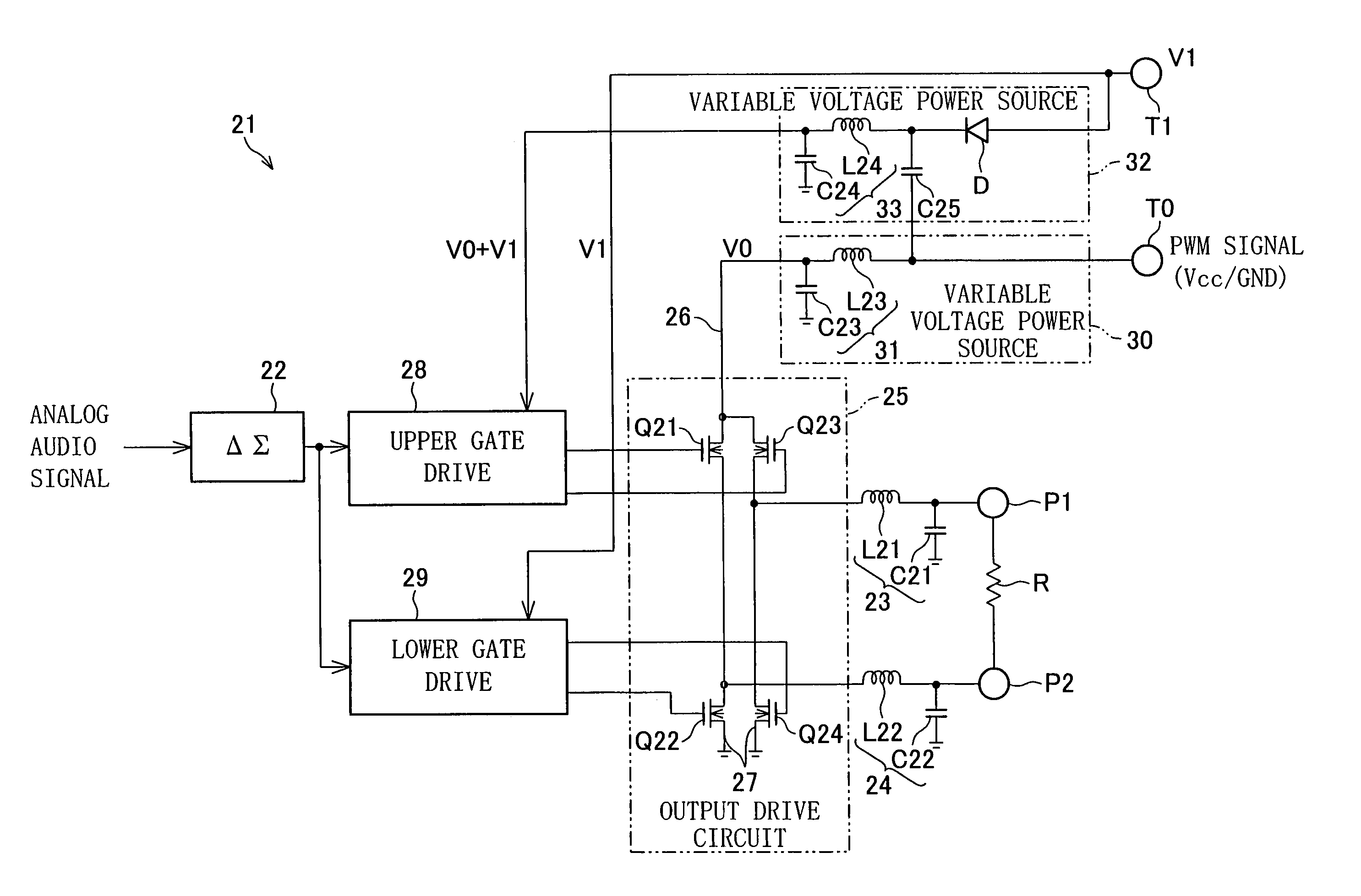
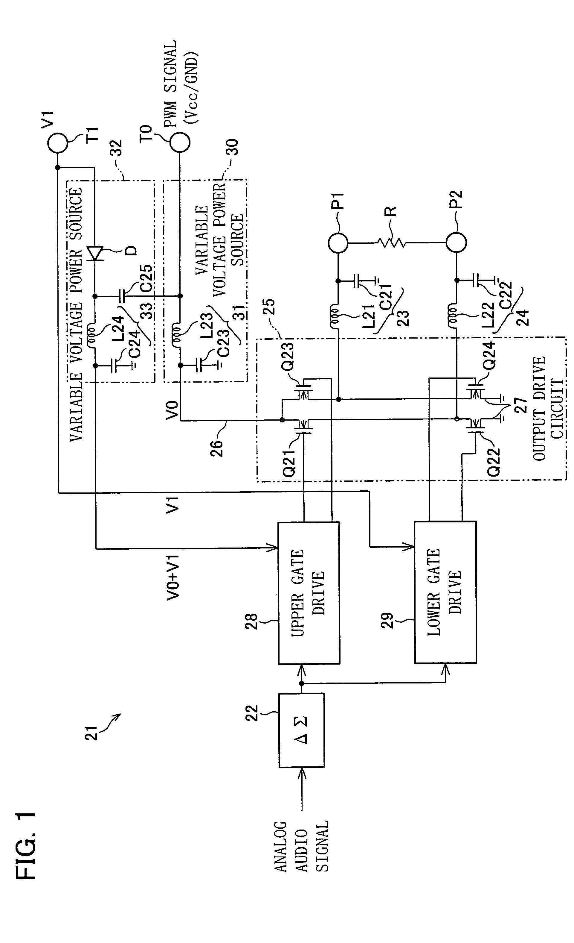
[0047]FIG. 1 is a block diagram showing an arrangement of a digital amplifier 21 as the present example.

[0048]The digital amplifier 21 performs voltage amplification (amplitude conversion) after causing a ΔΣ block 22 to convert an analog audio signal into a 1-bit digital signal such as PDM and PWM, and causes low pass filters 23 and 24 to convert the 1-bit digital signal into an analog signal again, thereby performing the power amplification with high efficiency. Further, the power amplification is performed by causing (i) a series circuit of output transistors Q21 and Q22 each of which is constituted of NMOSFET intervening between a high-level power source line 26 and a low-level power source line 27 and (ii) a series circuit of output transistors Q23 and Q24 each of which is constituted of NMOSFET intervening between the high-level power source line 26 and the low-l...

example 2

[0068]The following description will explain another example of the present invention with reference to FIG. 3 to FIG. 6.

[0069]FIG. 3 is a block diagram showing an arrangement of a digital amplifier 11 of the present example.

[0070]The digital amplifier 11 which is a 1-bit digital amplifier includes a digital signal source 1, a ΔΣ modulation circuit 2, a gate drive circuit 3, an output full-bridge circuit 4, a low pass filter (LPF in FIG. 3) 5, a variable voltage power source 6, and a micro computer 7.

[0071]The digital signal source 1 is a portion for receiving a digital and / or an analog audio signal, and has an amplitude adjustment function. In order to adjust an amplitude of an audio signal by performing a digital process on the basis of amplitude adjustment data outputted from the micro computer 7 as an amplitude adjustment function, the digital signal source 1 has a multiplier 11a as amplitude variation means for multiplying a multiplication coefficient (scale factor) set in the ...

example 3

[0115]The following description will explain still another example of the present invention with reference to FIG. 7.

[0116]FIG. 7 is a block diagram showing a minidisk device as a digital signal storage / reproduction device of the present example.

[0117]As shown in FIG. 7, in the minidisk device, a disk 41 which is a rewritable magnet-optical storage medium is used. First, specifications of storage / reproduction of the disk 41 is described. A whole storage surface of the disk 41 stores sound data such as tunes, i.e., data set, constituted of information datum related to each other, in which addresses with sequential numbers have been set in advance as storage units.

[0118]Further, the storage surface of the disk 41 has a U-TOC (User-Table Of Content) region, described later, which stores (i) information of address numbers of tunes and (ii) list information such as a title of the tune and a tune number (set number) both of which facilitate retrieval of stored tunes.

[0119]Specifications o...


PUM


Abstract

A digital amplifier causes a gate drive circuit to drive output transistors, and switches a power source voltage supplied from a variable voltage power source, thereby amplifying an amplitude of a 1-bit digital signal outputted from a ΔΣ block. A variable voltage power source varies a driving voltage, by which an upper gate drive circuit drives output transistors, as a voltage obtained by adding (i) a constant voltage supplied to a lower gate drive circuit to (ii) a power source voltage, so as to correspond to the power source voltage. Thus, the driving voltage is minimized without influencing a switching operation of the output transistors. As a result, it is possible to reduce power consumption of the upper gate drive circuit in turning down the volume.

Description

TECHNICAL FIELD[0001]The present invention relates to volume control of a digital amplifier constituted of a D-class amplifier or the like which drives a switching element by using a PDM (Pulse Density Modulation) signal or a PWM (Pulse Width Modulation) signal and performs high-efficiency power amplification of an audio signal by using the switching element in a saturation range.BACKGROUND ART[0002]Conventionally, a high-efficiency power amplifier described above is categorized into the following arrangements: (i) an arrangement in which an amplitude of a signal is adjusted in a signal source, and (ii) an arrangement in which an amplitude of a signal is adjusted in an amplifier section for amplifying a 1-bit digital signal that has been subjected to digital sigma modulation. FIG. 8 shows a high-efficiency power amplifier having the former arrangement, and FIG. 9 shows a high-efficiency power amplifier having the latter arrangement.[0003]In the arrangements shown in FIG. 8 and FIG. ...

Claims


Application Information

Patent Timeline
Patent Type & Authority Patents(United States)
IPC IPC(8): H03F3/38H03F3/217H03G1/00H03G3/00H03G3/30
CPCH03F3/2171H03F3/2173H03G3/3021H03G1/0088H03G3/004H03F2200/331
Inventor ISHIZAKI, HIROYUKI
Owner SHARP KK
Why Eureka
Try Eureka