

Fuel control system for a dual fuel internal combustion engine
a control system and internal combustion engine technology, applied in the direction of braking system, position/direction control, fuel supply apparatus, etc., can solve the problems of exacerbated problems, inefficient combustion of conventional internal combustion engines, and particularly inefficient compression ignition engines that use diesel fuel
- Summary
- Abstract
- Description
- Claims
- Application Information
AI Technical Summary
Benefits of technology
Problems solved by technology
Method used
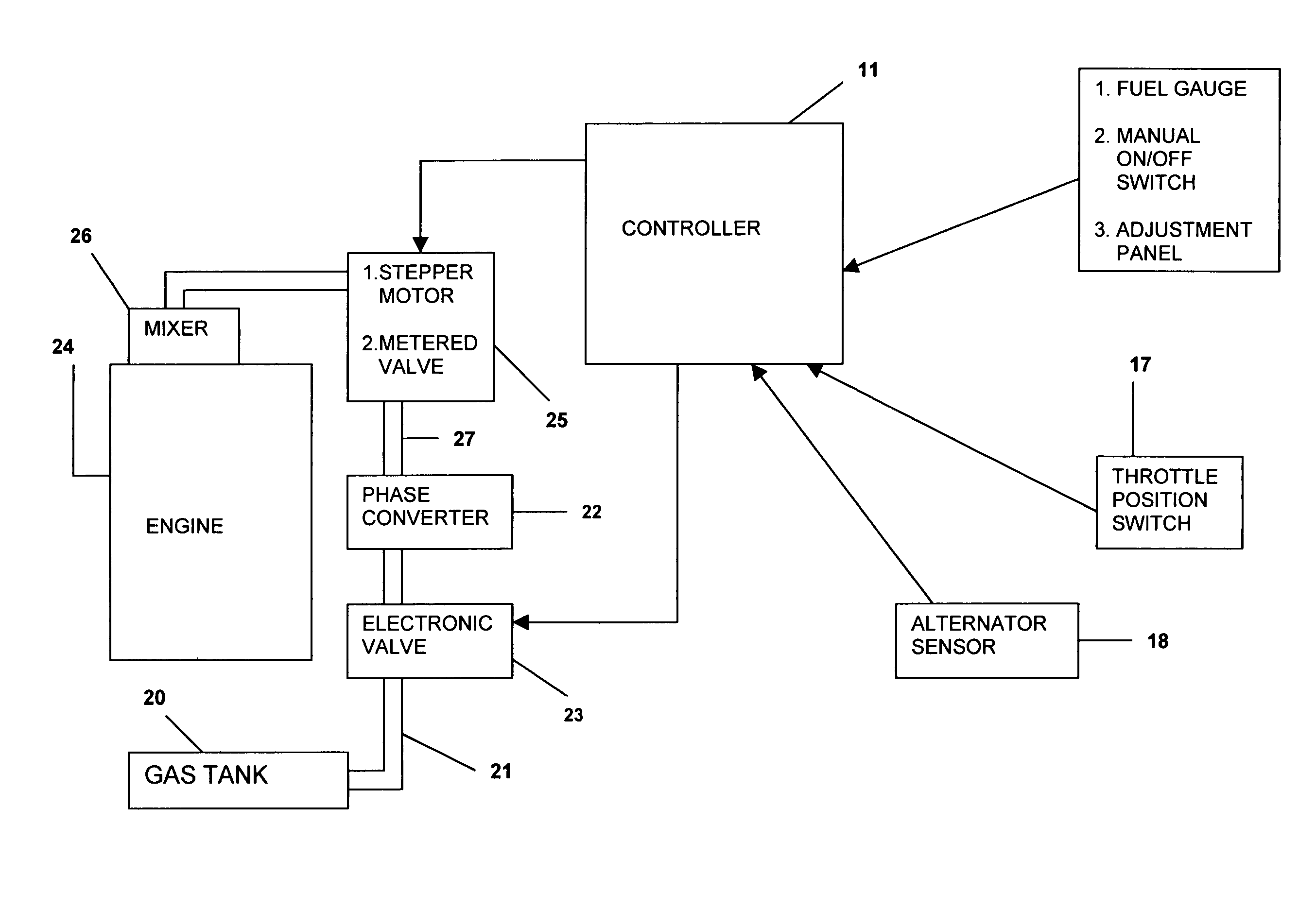
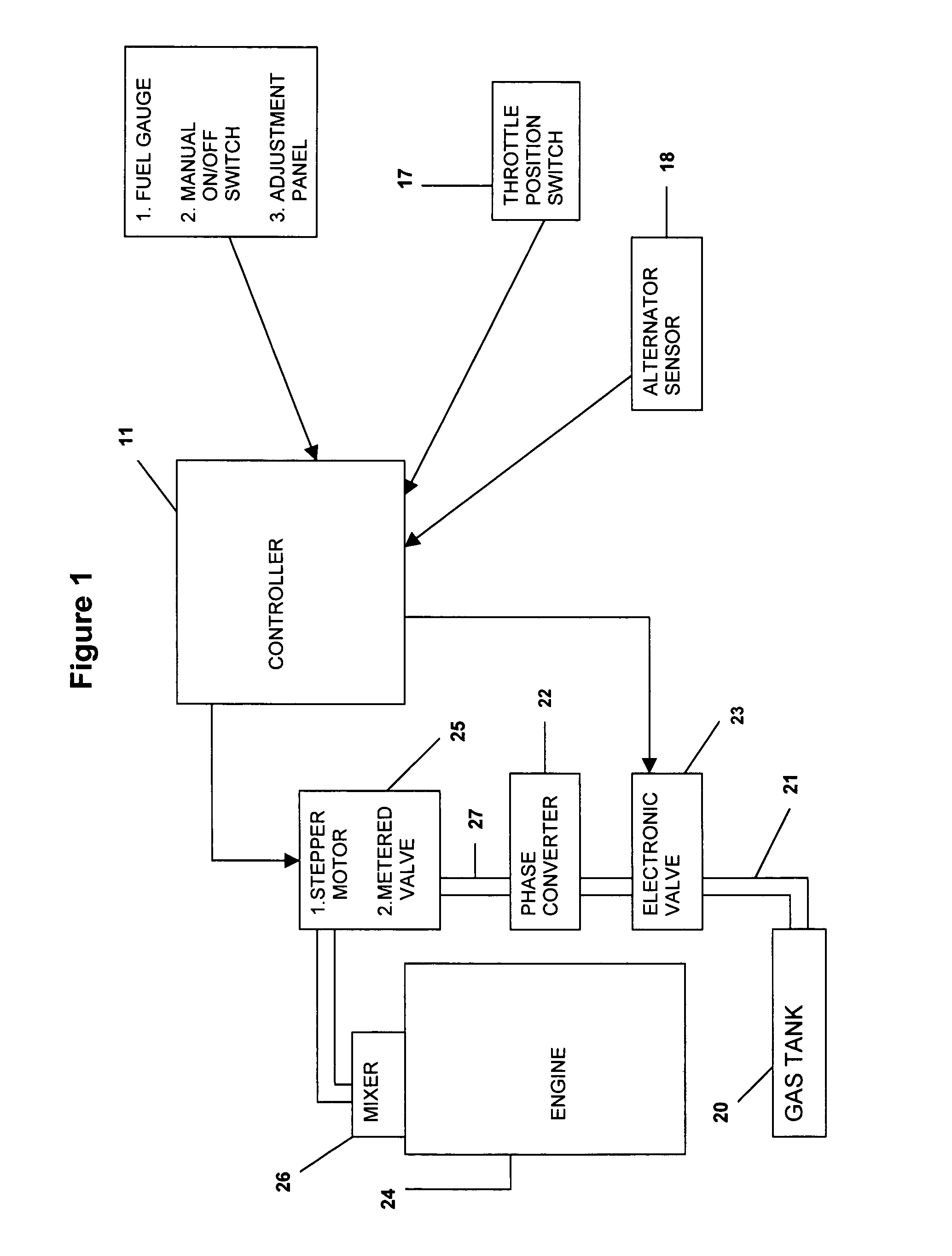
Image

Examples
experiment 1
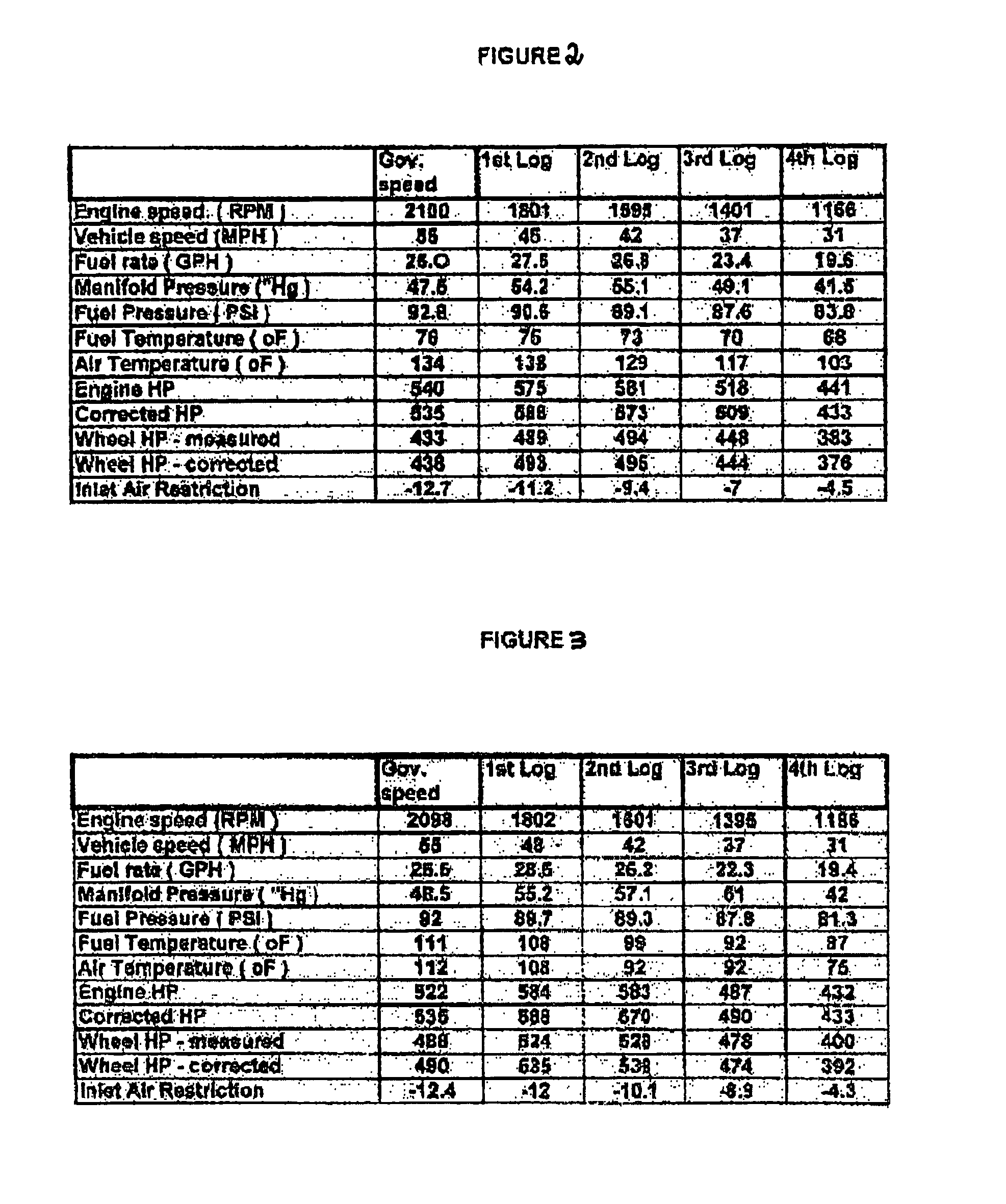
[0041]To determine the effect of the fuel control system on a dual fuel combustion engine, a vehicle with a dual fuel engine was tested with and without engagement of the fuel control system under similar conditions. The engine tested was a Caterpillar C-15 air to air after-cooled, direct injection diesel engine and the vehicle configuration was a Fuller-RTLQ20918B manual transmission with two drive axles and an axle ratio of 4.56. The weight on the axles was 8000 kg and radial tyres with a highway tread were used. The gas used as the supplementary fuel was propane.
[0042]The results of the experiment are shown in FIGS. 2 and 4 for the vehicle when no fuel control system was engaged and FIGS. 3 and 5 for the vehicle when the fuel control system was engaged. With engagement of the fuel control system, a comparatively higher engine horsepower was achieved by more efficient combustion of the fuel. Thus to achieve the same power as a conventional diesel engine, a dual fuel diesel engine ...
experiment 2
[0043]A further experiment was conducted using a SCANIA 113 vehicle with an 11 liter diesel engine. The vehicle comprised a trailer and hauled a load from Brisbane to Darwin and return. A comparison was made of using diesel only and diesel supplemented with LPG. Without engagement of the fuel control system the diesel consumption was 1.7 km / L and with using the dual fuel system the diesel and LPG consumption was 2.2 km / L. With the use of diesel and LPG and employment of the dual fuel control system, the exhaust emissions were comparatively cleaner and there was no obvious soot deposited on the trailer. With the dual fuel system the engine ran at a temperature 4 degrees cooler than if diesel was used alone. With a comparatively cooler engine the vehicle was able to sustain hard pulling in hot conditions such as driving through hot and adverse conditions. Without using a dual fuel system the vehicle would normally be stopped periodically to allow the engine to cool. As well, the engin...
PUM
 Abstract
Description
Claims
Application Information