
Nonlinear phase-shift compensation method and apparatus

a phase shift compensation and phase shift compensation technology, applied in the field of optical telecommunications, can solve the problems of severe nonlinear penalty in dms-based dense-wavelength-multiplexed (dwdm) transmissions, limited transmission distance of ulh transmission, and introduction of timing jitter, so as to reduce the nonlinear phase noise in psk systems, and reduce the nonlinear phase nois

Active Publication Date: 2006-06-13
WSOU INVESTMENTS LLC +1
View PDF4 Cites 11 Cited by
  • Summary
  • Abstract
  • Description
  • Claims
  • Application Information

AI Technical Summary

Benefits of technology

"The invention provides a method and apparatus for reducing nonlinear phase noise in optical transmission systems. This is achieved by adding a phase shift proportional to the pulse power of each optical pulse, which reduces the nonlinear phase noise caused by SPM and ASE. The invention also uses quadratic nonlinear materials, such as PPLN, to generate the necessary nonlinear phase shifting. Additionally, a phase modulator is used to modulate the phase of the data pulses sent to a PSK receiver, with the phase modulation being data driven and designed to be proportional to the detected data pulse intensity and opposite in sign to the nonlinear phase shift caused by SPM. The use of NPSC devices in optical transmission systems results in significant performance improvement."

Problems solved by technology

The transmission distance of ULH transmission is limited by amplified spontaneous emission (ASE) noise and fiber nonlinearities.
However, there exists a severe nonlinear penalty in DMS-based dense-wavelength-multiplexed (DWDM) transmissions, namely inter-channel XPM which introduces severe timing jitter.
However, the performance of such systems is generally limited by the Gordon-Mollenauer effect, in which ASE power noise is converted into phase noise by self-phase modulation (SPM).
A distributed nonlinear compensator is, however, extremely complicated, and therefore very expensive.

Method used


Image

  • Nonlinear phase-shift compensation method and apparatus
  • Nonlinear phase-shift compensation method and apparatus
  • Nonlinear phase-shift compensation method and apparatus

Examples


Embodiment Construction

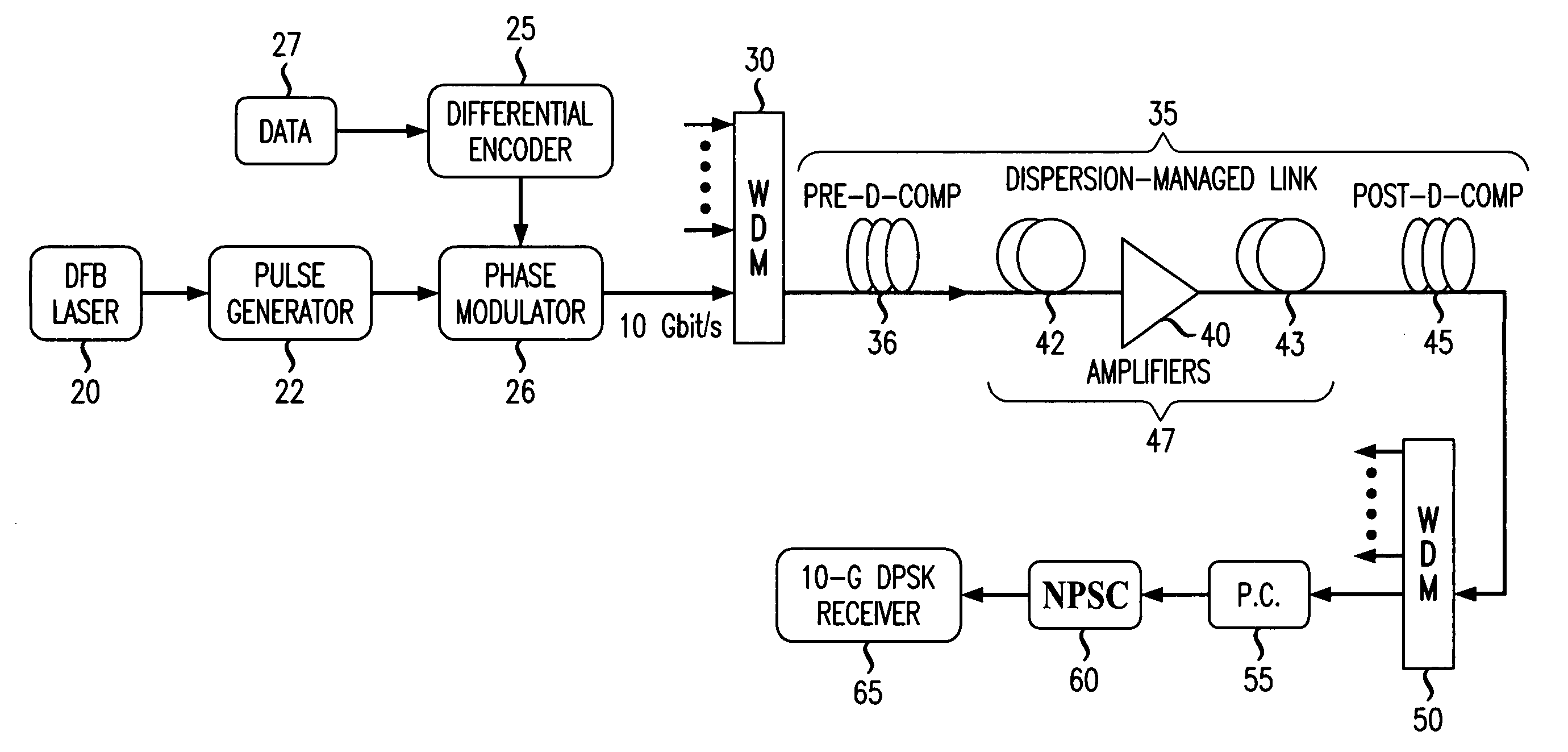
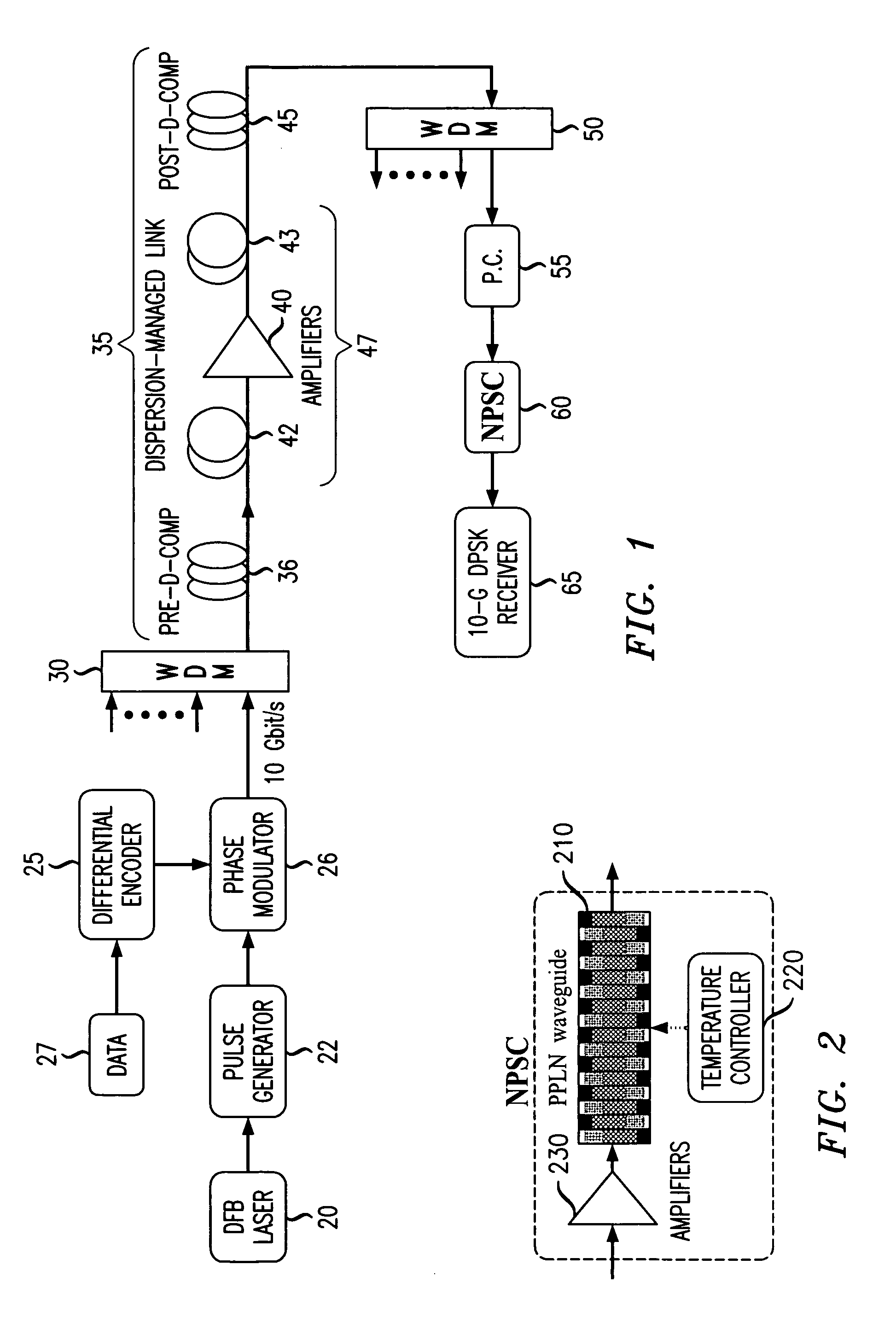
[0019]A schematic diagram of a DMS-DPSK system 10 according to one embodiment of the invention is shown in FIG. 1. On the transmitter side, a DBF laser 20 and a pulse generator 22 are used to generate a pulse train (e.g., with a repetition rate of 10 GHz and a duty cycle of 33% (pulse full width half maximum (FWHM) of 33 ps)). A 10 Gb / s differential data encoder 25 and a phase modulator 26 are provided to encode data from data source 27 in the phase of the optical pulses in such a way that every 0(1) in the original data is represented by a π(0) shift in the relative phase of two adjacent pulses. A multiplexer 30 is used to multiplex several WDM channels before being launched into a dispersion-managed link 35.

[0020]On the receiver side, the WDM channels are de-multiplexed using a demultiplexer 50. A polarization controller 55, which may comprise three waveplates, is preferably used to rotate the polarization of the signal wave such that the signal output polarization matches well wi...


PUM

PropertyMeasurementUnit
communication wavelengthaaaaaaaaaa
distanceaaaaaaaaaa
transmission distanceaaaaaaaaaa

Abstract

A nonlinear phase-shift compensation method and apparatus is provided for improving system performance in optical transmission systems. The apparatus includes a phase-shift compensating device that provides a partial compensating phase shift to reduce the nonlinear phase noise resulting from self-phase modulation and amplified spontaneous emissions in an optical transmission system.

Description

FIELD OF INVENTION[0001]This invention relates generally to the field of optical telecommunications, and in particular, to a method and apparatus for improving optical transmission performance by reducing phase jitter in optical transmission systems using a nonlinear phase-shift compensator.BACKGROUND OF THE INVENTION[0002]Ultra-long-haul (ULH) optical transmission is of crucial importance to increase the flexibility of future optical networks. The transmission distance of ULH transmission is limited by amplified spontaneous emission (ASE) noise and fiber nonlinearities. The use of dispersion-managed solitons (DMS) and other signal formats in such systems has attracted attention because of the potential for increased transmission performance. DMS systems balance self-phase-modulation (SPM) with fiber dispersion, and avoid intra-channel cross-phase-modulation (XPM) and four-wave-mixing (FWM) by maintaining a moderate degree of pulse breathing. However, there exists a severe nonlinear...

Claims


Application Information

Patent Timeline
Patent Type & Authority Patents(United States)
IPC IPC(8): H04B10/02G02B5/00G02F1/03G02F1/355H04B10/18G02F1/35G02F1/377H04B10/06
CPCH04B10/255
Inventor LIU, XIANGMCKINSTRIE, COLIN JMOLLENAUER, LINN FREDERICKSLUSHER, RICHART ELLIOTTWEI, XINGXU, CHUNHUI
Owner WSOU INVESTMENTS LLC
Learn More