
Mass chromatograph

a mass chromatograph and mass spectrometry technology, applied in mass spectrometers, separation processes, instruments, etc., can solve the problems of contaminated ion sources, insufficient consideration of dilution in prior art technologies, and contamination of ion sources, so as to achieve easy contamination and high sensitivity analysis

Active Publication Date: 2006-06-20
HITACHI LTD
View PDF6 Cites 47 Cited by
  • Summary
  • Abstract
  • Description
  • Claims
  • Application Information

AI Technical Summary

Benefits of technology

The invention provides an APCI source and a mass spectrometer that are not easily contaminated, and can efficiently analyze high sensitivity samples without being affected by impurities. The sample gas is directly introduced into the field of an ion-molecule reaction, resulting in high efficiency of ionization and introduction of the resulting sample ion into the mass analysis portion. This prevents dilution of the sample gas before its introduction into an ion source and contamination of the ion source, allowing for high sensitivity analysis. The mass spectrometer is constructed in a way that the APCI source is separated from the sample gas by a lead-out electrode and a differential exhaust portion, preventing contamination of the ion source. The invention can also provide an APCI source that does not generate contamination and a mass spectrometer using this source for high sensitivity analysis.

Problems solved by technology

As described above, the prior art technologies do not sufficiently take dilution into consideration when the outflow gas from GC is introduced into the APCI source, and are not free from the problem of the drop of the sensitivity.
Consequently, the ion source is contaminated and an S / N ratio gets decreased.
Therefore, maintenance such as frequent cleaning of the ion source is necessary and hinders efficient analysis.
However, the problem of the drop of sensitivity occurs when the gas from GC is merely mixed with the primary ion generation gas.

Method used


Image

  • Mass chromatograph
  • Mass chromatograph
  • Mass chromatograph

Examples


first embodiment

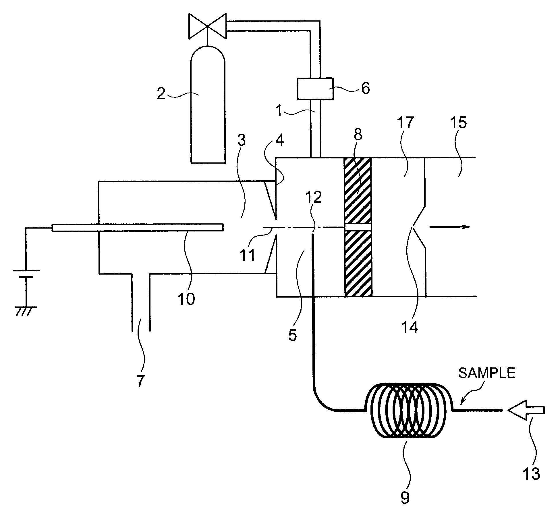
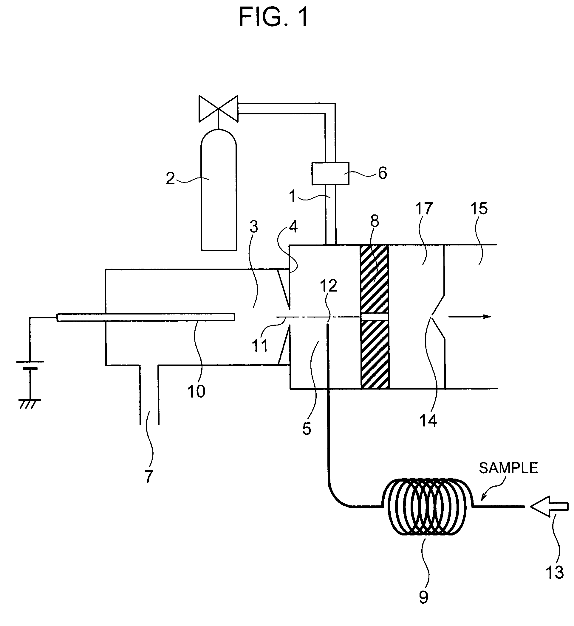
[0038]FIG. 1 is a sectional view showing a construction of a mass spectrometer according to a first embodiment of the invention. This mass spectrometer (GC / APCI / MS) is a high sensitivity apparatus that ionizes sample molecules (sample gas) separated by a GC column by an APCI source and analyzes the mass.

[0039]A first ionization portion 3 and a second ionization portion 5 are separated from each other by a first partition (lead-out electrode 4) having a primary ion introduction aperture 11 through which a primary ion passes. The second ionization portion 5 is an area that is interposed by the first partition and a second partition that has a sample ion movement aperture 8 through which a sample ion of a sample gas generated by the reaction between the sample molecule and the primary ion (hereinafter called “ion-molecule reaction”) inside the second ionization portion 5 passes.

[0040]The mass spectrometer according to the first embodiment includes the first ionization portion 3, the se...

second embodiment

[0092]FIG. 5 is a sectional view showing a construction of a mass spectrometer according to the second embodiment of the invention. The construction of the second embodiment is effective for executing positive ionization of the sample gas.

[0093]In the second embodiment, the sample gas introduced from the aperture 12 at the end of the GC column 9 is introduced into a corona discharge portion (area indicated by dotted line in FIG. 2). The needle electrode 10 is arranged inside the ionization portion 18 and the primary ion generation gas introduction piping 1 is connected at a position far from the sample ion movement aperture 8 (position on the root side of needle electrode 10) on the opposite side to the tip end of the needle electrode 10 inside the ionization portion 18. The primary ion generation gas from the gas cylinder 2 is introduced through the primary ion generation gas introduction piping 1 into the ionization portion 18 while its flow rate is regulated by the mass flow cont...

third embodiment

[0101]FIG. 6 is a sectional view showing a construction of a mass spectrometer according to the third embodiment of the invention. The construction of the third embodiment is effective for executing positive ionization of the sample components having a small reaction rate constant in the ionization reaction.

[0102]The difference of the third embodiment from the first embodiment resides in the arrangement position of the center of the aperture 12 at the end of the GC column 9, the arrangement position of the primary ion generation gas introduction piping 1 and exhausting of the gas from an ion passage aperture 20 in place of the primary ion generation gas exhaust piping 7. In the third embodiment, the sample gas introduced from the aperture 12 at the end of the GC column 9 is introduced into the corona discharge portion (area indicated by dotted line in FIG. 6) in the same way as in the second embodiment.

[0103]The ionization portion 18′ in which the needle electrode10 is arranged is c...


PUM

PropertyMeasurementUnit
flow rateaaaaaaaaaa
flow rateaaaaaaaaaa
diameteraaaaaaaaaa

Abstract

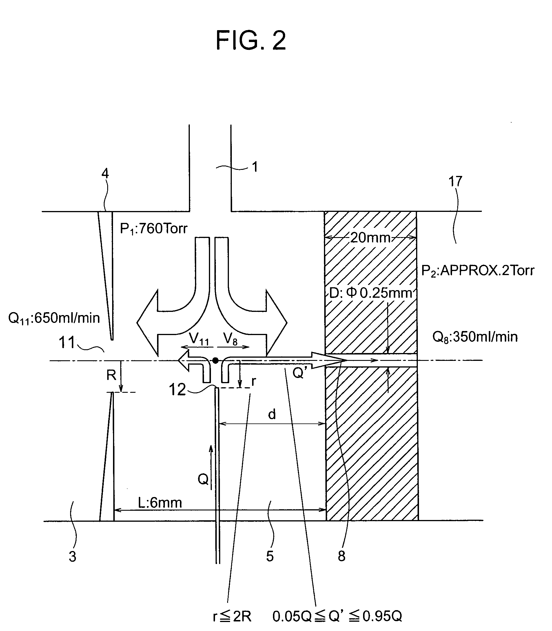
A mass spectrometer has an atmospheric pressure chemical ionization source that includes a first ionization portion including a needle electrode, for generating a primary ion by discharge of the needle electrode a primary ion introduction aperture, and a second ionization portion including an introduction aperture, for generating a sample ion by the reaction between the primary ion and the sample gas introduced from an end of a column of gas chromatography, a sample ion movement aperture; and a mass analysis portion; wherein the end is arranged at a position satisfying the relation r≦2R where R is a radius of an inner diameter of the aperture and r is a distance between an axis connecting the center of the aperture and the center of the aperture, and the end.

Description

INCORPORATION BY REFERENCE[0001]The present application claims priority from Japanese application JP 2004-269112 filed on Sep. 16, 2004, the content of which is hereby incorporated by reference into this application.BACKGROUND OF THE INVENTION[0002]1. Field of the Invention[0003]This invention relates to an atmospheric pressure chemical ionization mass spectrometry for analyzing a sample gas separated by gas chromatography.[0004]2. Description of the Related Art[0005]In the description to follow, gas chromatography will be abbreviated as “GC”, a mass spectrometer, as “MS”, an apparatus including the combination of the gas chromatography and the mass spectrometer, as “GC / MS”, an atmospheric pressure chemical ionization source, as “APCI source”, an atmospheric pressure chemical ionization mass spectrometer (apparatus including the combination of APCI and MS), as “APCI / MS”, a chemical ionization source, as “CI source”, an electron impact ion source, as “EI source”, and an apparatus inc...

Claims


Application Information

Patent Timeline
Patent Type & Authority Patents(United States)
IPC IPC(8): H01J49/26G01N27/62
CPCH01J49/145H01J49/0422H01J49/168G01N30/7213
Inventor YAMADA, MASUYOSHIWAKI, IZUMIKASIMA, HIDEO
Owner HITACHI LTD
Learn More