Electrostatic discharge protection structures having high holding current for latch-up immunity

a protection structure and electrostatic discharge technology, applied in the direction of emergency protection circuit arrangement, transistor, etc., can solve the problem of uncontrollable triggering, voltage shorting to ground, and unintentional latching of scrs as esd protection devices during normal operation conditions, etc., to achieve high holding current

Inactive Publication Date: 2006-06-20
SOFICS BVBA
View PDF32 Cites 62 Cited by
  • Summary
  • Abstract
  • Description
  • Claims
  • Application Information

AI Technical Summary

Benefits of technology

[0009]The disadvantages heretofore associated with the prior art are overcome by various embodiments of an electrostatic discharge (ESD) protection circuit in a semiconductor integrated circuit (IC) having protected circuitry. The ESD protection circuit has a high holding current for latch-up immunity. In one embodiment, the ESD protection device includes a silicon controlled rectifier (SCR) coupled between a protected supply line of the IC and ground. A trigger device is coupled from the supply line to a first gate of the SCR, and a first substrate resistor is coupled between the first gate and ground. A first fixed shunt resistor is coupled between the first gate and ground, where the shunt resistor has a resistance value lower than the substrate resistor. During either a powered-on...

Problems solved by technology

One concern in the industry about using SCRs as ESD protection devices is unintentional latch-up during normal operating conditions.
Latch-up is an uncontrolled triggering of an (parasitic) SCR structure on the IC during normal operation, such that the supply voltage is shorted to ground.
A latch-up condition could lead to very high currents from the power supply that may permanently damage the IC.
A first disadvantage for such a high holding voltage is that a considerable number of serial coupled diodes would be a needed, which requires additional area (i.e., real estate) on the IC.
A second disadvantage is that the serial diodes do not add func...

Method used


Image

  • Electrostatic discharge protection structures having high holding current for latch-up immunity
  • Electrostatic discharge protection structures having high holding current for latch-up immunity
  • Electrostatic discharge protection structures having high holding current for latch-up immunity

Examples


third embodiment

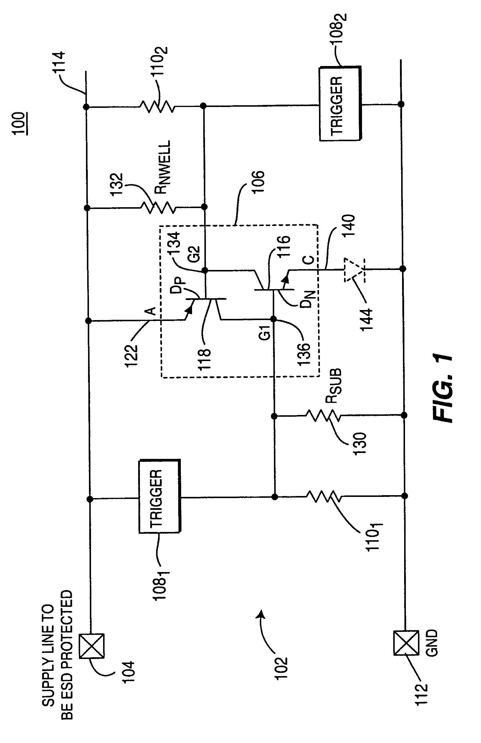
[0033]Alternatively, where the second gate 134 of the SCR 106 is used, a second trigger device 1082 is coupled between the second gate G2134 and ground 112, while a second low resistance shunt resistor 1102 is coupled from the voltage supply line 114 to the second gate G2134. In a third embodiment and as shown below in FIG. 3, both first and second trigger devices 1081 and 1082 and the low resistance shunt resistors 1101 and 1102 are respectively coupled to the first and second gates 136 and 134 as described above.

[0034]In one embodiment, the trigger devices 108 may be MOS devices, e.g., a grounded gate NMOS (GGNMOS) device or a source-connected gate PMOS (SGPMOS) device. Alternatively, the trigger devices may be a Zener diode in a reverse conduction direction, a small diode chain in a forward conduction direction, or other devices typically used in the art.

[0035]In one embodiment, the shunt resistors 110 are external on-chip resistors fabricated from, for example, silicided poly-si...

second embodiment

[0050]FIG. 3 depicts a schematic block diagram of the HHISCR protection device 302 having an actively controlled latch-up circuit 312. The configuration of the HHISCR protection device 302 is configured the same as the HHISCR protection device 102 of FIG. 1, except that the shunt resistors 3101 and 3102 are variable resistors. The variable shunt resistors 310 are fabricated from a three terminal semiconductor device (e.g., MOS device) having either linear or non-linear resistance characteristics.

[0051]Additionally, a first latch-up (LU) control circuit 3121 is coupled to the first variable shunt resistor device 3101. The latch-up control circuit 3121 is also coupled between the supply line to be protected 104 and ground 112. As will be discussed in further detail below, the latch-up control circuit 312 is designed to detect whether or not there is power on the supply line 104 to be protected, as well as adjust the triggering and holding currents above or below the latch-up current o...

first embodiment

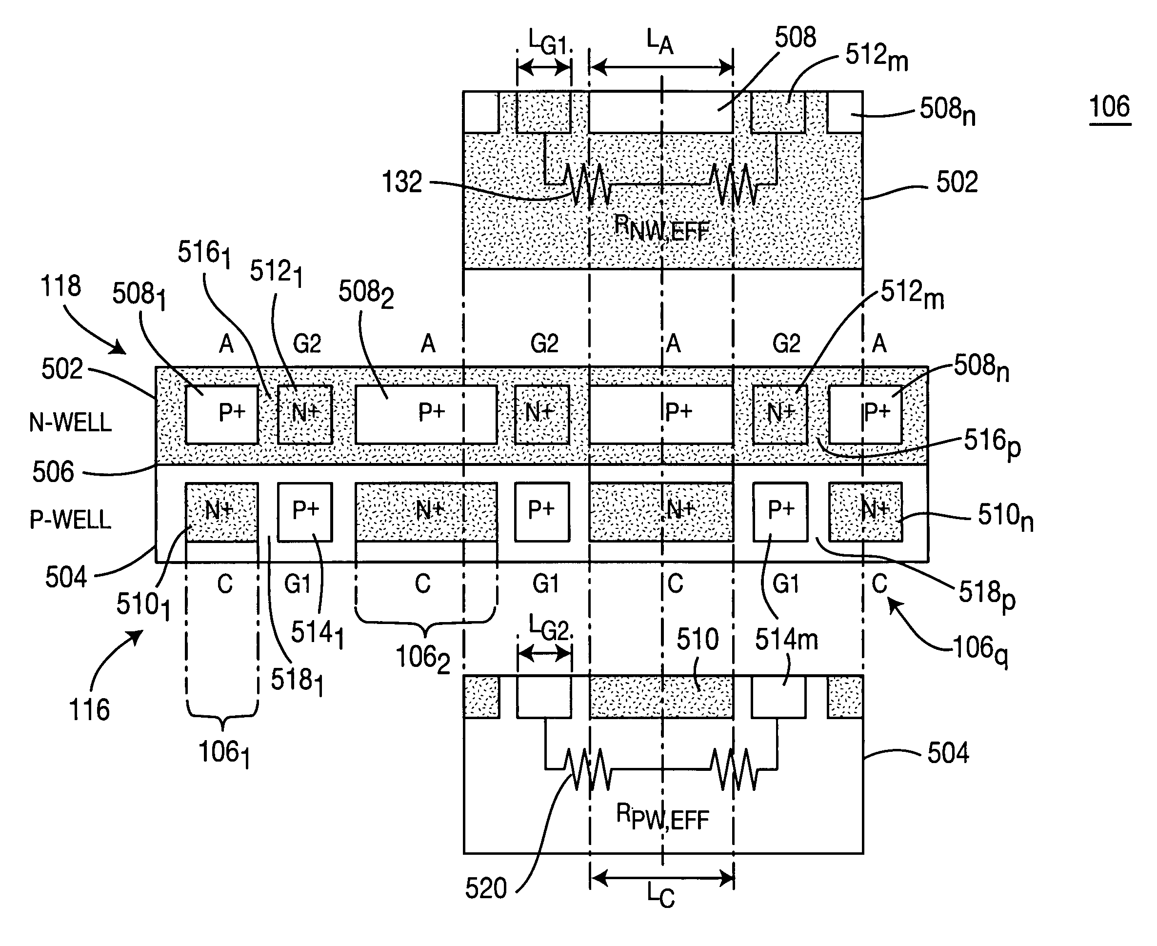
[0067]FIG. 6 depicts a detailed schematic diagram of the actively controlled HHISCR ESD protection device 302 of FIG. 3. FIG. 6 should be viewed together with FIG. 3. The HHISCR ESD protection device 602 depicts a detailed schematic diagram of one embodiment of the latch-up control circuits 312 that are coupled to the SCR 106, as shown in the block diagram of FIG. 3. In particular, the HHISCR ESD protection device 602 comprises the SCR 106 having an equivalent resistor RId 604 representing the parallel-coupled shunt resistor 110 (if present) and the inherent P-substrate resistance Rsub 130, which are coupled between the first gate 136 and ground 112. The equivalent resistor RId 604 has a resistance value of approximately 1 Kohm.

[0068]FIG. 6 illustratively shows the trigger devices 108 and the latch-up control circuits 312 for both SCR gates G1 and G2136 and 134. The HHISCR ESD protection device 602 is used to provide a high triggering and holding current under normal IC operation (a...


PUM


Abstract

An electrostatic discharge (ESD) protection device having high holding current for latch-up immunity. The ESD protection circuit is formed in a semiconductor integrated circuit (IC) having protected circuitry. The ESD protection device includes a silicon controlled rectifier (SCR) coupled between a protected supply line of the IC and ground. A trigger device is coupled from the supply line to a first gate of the SCR, and a first substrate resistor is coupled between the first gate and ground. A first shunt resistor is coupled between the first gate and ground, wherein the shunt resistor has a resistance value lower than the substrate resistor.

Description

CROSS REFERENCES[0001]This application is a division of U.S. patent application Ser. No. 10 / 099,263, filed Mar. 15, 2002 now U.S. Pat. No. 6,803,633, which claimed the benefit of U.S. Provisional Applications, Ser. No. 60 / 276,420, filed Mar. 16, 2001; Ser. No. 60 / 280,343, filed Mar. 30, 2001; Ser. No. 60 / 280,344, filed Mar. 30, 2001; Ser. No. 60 / 280,439, filed Mar. 30, 2001; Ser. No. 60 / 280,441, filed Mar. 30, 2001; and Ser. No. 60 / 280,443, filed Mar. 30, 2001; the contents of which are incorporated by reference herein.FIELD OF THE INVENTION[0002]This invention generally relates to the field of electrostatic discharge (ESD) protection circuitry, and more specifically, improvements for silicon controlled rectifier (SCR) circuits in the protection circuitry of an integrated circuit (IC).BACKGROUND OF THE INVENTION[0003]Silicon controlled Rectifiers (SCRs) have long been used over a broad range of technologies because of their superior performance. During an ESD event, the SCR is consi...

Claims


Application Information

Patent Timeline
IPC IPC(8): H01L23/62H01L29/74H01L21/822H01L21/8238H01L27/02H01L27/04H01L27/06H01L27/092H02H9/00
CPCH01L27/0292H01L27/0262
Inventor MERGENS, MARKUS PAUL JOSEFRUSS, CORNELIUS CHRISTIANARMER, JOHNVERHAEGE, KOEN GERARD MARIAJOZWIAK, PHILLIP CZESLAW
Owner SOFICS BVBA
Why Eureka
Try Eureka