Method and apparatus for a transceiver having a constant power output

a technology of constant output power and transceiver, which is applied in power management, dc level restoring means or bias distortion correction, baseband system details, etc., can solve the problems of increasing the overall cost of the resulting transceiver, non-cmos power amplifiers cannot be formed on the same integrated circuit chip as the components of the transmitter and/or transceiver, and achieving the effect of preventing output power

Inactive Publication Date: 2006-06-20
THE CONNECTIVITY PATENT TRUST
View PDF18 Cites 12 Cited by
  • Summary
  • Abstract
  • Description
  • Claims
  • Application Information

AI Technical Summary

Benefits of technology

[0011]It is another object of the invention to provide an apparatus and method that allows for gradual step increases in output power to avoid the output power from exceeding a predetermined maximum output power.
[0016]Once achieved, output power is prevented from exceeding the predetermined maximum by decreasing the gain by a predetermined amount at the beginning of transmission of each subsequent packet, so that the output power can be lowered by an amount corresponding to the decreased gain on a per-packet basis. Alternatively, the comparator can be strobed during the training sequence of symbols within each packet at the results of the comparison used to back-off the output power by at least one or maybe more steps during the transmission of the next packet.
[0017]The variable gain amplifier implemented allows for the power control circuit to change the gain in small incremental steps, thereby allowing the power control algorithm implemented by the power control circuit to operate.

Problems solved by technology

While such designs allow for a power amplifier that has the desired amplification characteristics, they do so at the expense of cost.
Not only is a GaAs, SiBJT or other non-CMOS power amplifier costlier than a transistor in a CMOS integrated circuit, but the non-CMOS power amplifier cannot be formed on the same integrated circuit chip as the components of the transmitter and / or transceiver.
Both of these factors add to the overall cost of the resulting transceiver.
Nevertheless, a major disadvantage of CMOS power amplifiers is that they exhibit a wide range of power levels variation due to their sensitivity to thermal and process variations.
High efficiency and constant power levels in CMOS power amplifiers is impeded by the technologies low breakdown voltage, low current drive, and lossy substrate.
In such an environment, the above-described design cannot be used.
Since in order to take into account instances in which power will exceed the pre-specified maximum, the average output power must be much lower than that maximum, which degrades system performance to an unacceptable level.

Method used


Image

  • Method and apparatus for a transceiver having a constant power output
  • Method and apparatus for a transceiver having a constant power output
  • Method and apparatus for a transceiver having a constant power output

Examples


Embodiment Construction

[0023]Reference will now be made in detail to preferred embodiments of the invention, examples of which are illustrated in the accompanying drawings. Wherever convenient, the same reference numbers will be used throughout the drawings to refer to the same or like parts.

[0024]Other embodiments will be apparent to those skilled in the art from consideration of the specification and practice of the invention disclosed herein. It is intended that the specification and examples be considered as exemplary only, with a true scope of the invention being indicated by the following claims and equivalents.

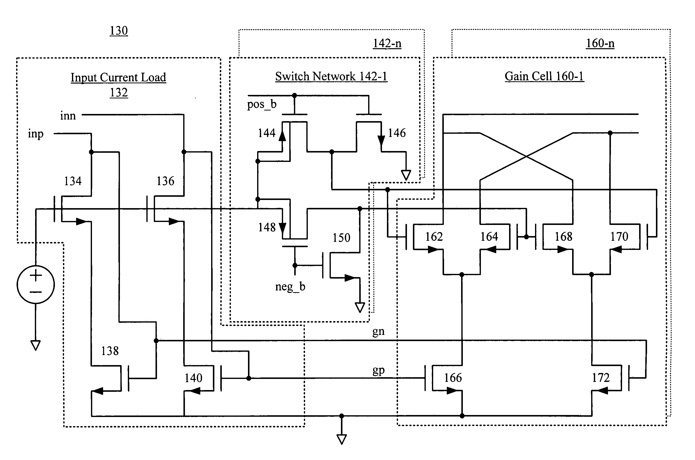
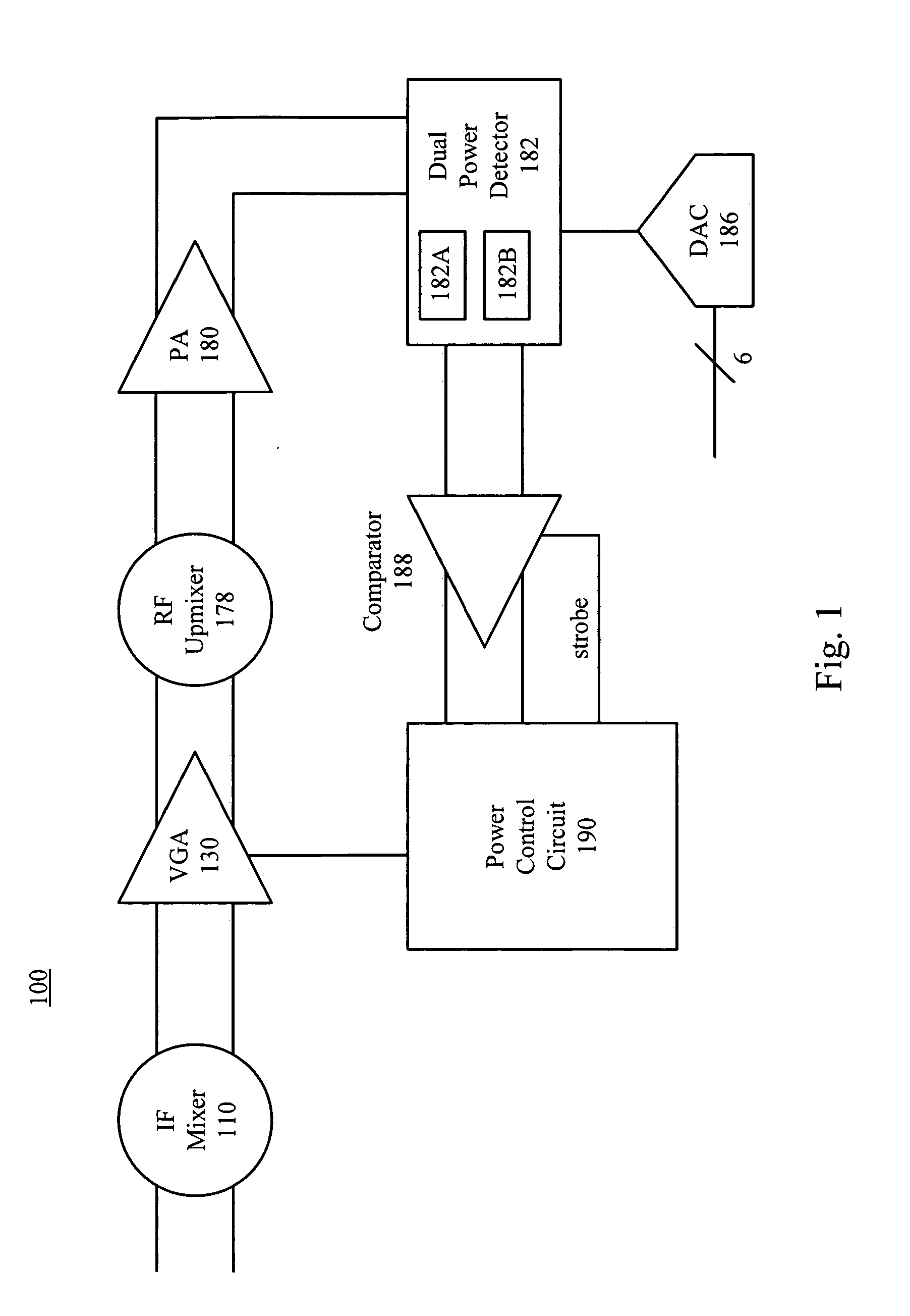
[0025]FIG. 1 illustrates a block diagram of an embodiment of a power control circuit 100. As shown in FIG. 1, IF upmixer 110 upconverts signals received by the transceiver to an IF frequency as is known, for example a 1 GigaHertz IF Frequency and a 5 GigaHertz RF frequency. After the IF upmixer 110, the IF variable gain amplifier (VGA) 130 which, in the preferred embodiment contains a 5 bit i...


PUM


Abstract

The present invention includes a transceiver and a method of operating the same that includes in the transmitter a power control circuit that operates on an analog differential signal containing data packets individually. The power control circuit initially transmits a series of data symbols with known values, periodically strobes the transceiver system for correct power levels and incrementally increases the power level of the transceiver until the optimal gain is reached, without exceeding the maximum output power.

Description

[0001]This application is related to and claims priority to U.S. Provisional Application No. 60 / 258,150 filed on Dec. 22, 2000.FIELD OF THE INVENTION[0002]The present invention is generally related to a complementary metal oxide semiconductor (CMOS) transceiver. More specifically, the present invention relates to a method and apparatus for achieving constant output power from a CMOS transceiver.BACKGROUND OF THE RELATED ART[0003]A transceiver is a well-known circuit, containing a transmitter and a receiver, which are thus capable of transmitting and receiving communication signals, respectively. Conventionally, the transmitter contains a power amplifier (PA) that provides the last stage of amplification of the signal to be transmitted.[0004]In most conventional designs, the power amplifier is implemented as a component that is physically separate from other parts of the transmitter and / or transceiver. Also, power amplifier's made from gallium arsenide (GaAs) or Silicon bipolar junct...

Claims


Application Information

Patent Timeline
Patent Type & Authority Patents(United States)
IPC IPC(8): H04K1/02H04L25/03H04L25/49H03G3/30H04B1/04H04B7/005
CPCH03F1/223H03F3/24H03F3/45475H04W52/362H04W52/367H03G3/3042H03F2203/45128H03F2203/45274H04W52/52H04B2001/0416H04W52/286
Inventor KACZYNSKI, BRIAN J.
Owner THE CONNECTIVITY PATENT TRUST
Why Eureka
Try Eureka