
Supplying water to a reticulation system from different sources

a technology of reticulation system and water supply, which is applied in the direction of liquid transfer device, machine/engine, process and machine control, etc., can solve the problems of inability to supply water to buildings, discourage rainwater collection in urban areas, etc., and achieve the effect of preventing water contamination and upstream cross contamination of mains water

Inactive Publication Date: 2006-06-27
URBAN RAINWATER SYST PTY LTD (AU)
View PDF7 Cites 35 Cited by
  • Summary
  • Abstract
  • Description
  • Claims
  • Application Information

AI Technical Summary

Benefits of technology

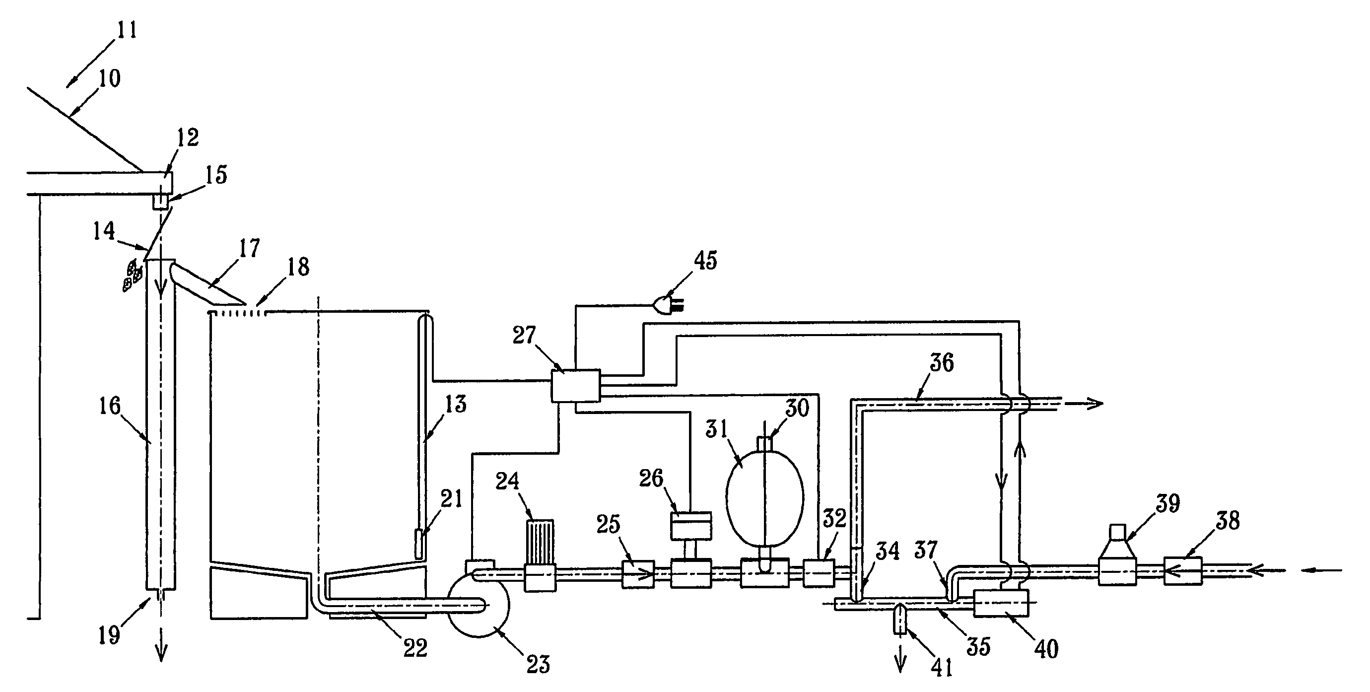
[0033]When the pressure is above a preset value, the control means switches off the pump either immediately or after a preset period of continued pumping. Pressure is maintained downstream of the non-return valve until water draw off causes it to be lowered, whereupon the pressure sensor will detect this state of lowered pressure and send a signal to the controller to cause the pump to be restarted. Preferably an accumulator is installed downstream of the non-return valve in the tank water system so as to reduce the frequency of the pump restarting. In the event that water is detected in the tank by the water level sensor and the operation of the pump does not cause the pressure detected by the pressure sensor to rise then the pump is turned off and the three port valve is switched to deliver mains supply water via the second port to the third outlet port. Thus water supply is maintained and pump damage is averted. A preferred form of the tank water system also includes a flow sensor downstream of the non-return valve which sends an electrical signal to the controller. In the event that a very low water flow occurs the output from this flow sensor can be used by the controller to delay repeated switching on of the pump as would otherwise be dictated by dropping pressure level.
[0035]The servo shuttle valve in a preferred form breaks supply from one inlet port before opening the other inlet port thereby preventing upstream cross contamination of mains water with tank water. In an alternative form, the servo shuttle valve may open one inlet port before closing the other inlet port thereby relying on upstream non-return valves in both systems to prevent water contamination.
[0036]The control means preferably receives input signals from the water sensor in the tank, the pressure sensor detecting the pressure of water within water tank supply line and the availability of mains electricity. The control means preferably has a battery backup in the event of failure of mains electricity so that there is electrical power to switch the servo shuttle valve from one position to another. The control means controls the operation of the pump and preferably turns the pump off when the water sensor detects that the level of water within the tank is below a predetermined level. In this situation the control means actuates the servo shuttle valve to close the first port and open the second and third ports. Where there is an accumulator, the non-return valve prevents backflow from the accumulator through the pump and back into the tank. The accumulator provides pressurized water on demand when the first port is open.
[0038]In the case that the pressure sensor is a switch it is preferable that it is of a kind that has some hysteresis in its switching behaviour, so that it switches on at a lower pressure when it switches off. This avoids unnecessary turning on and off of the pump.
[0048]Preferably there is a mains water system non-return valve upstream of the servo shuttle valve to open and close the mains water supply lines for providing mains water. The provision of a mains water system non-return valve acts as a further back flow prevention device to satisfy government requirements. There may also be a regulator upstream of the servo shuttle valve. There may preferably be a regulator downstream of the non-return valve but upstream of the servo shuttle valve. The regulator serves to prevent a change in flow rate between the switching from one water supply source to another.
[0069]Several forms of logic may be used by the controller in controlling the pump and three port valve of the water supply system. The logic systems are dependent on the sophistication of the water level sensing and whether a flow sensing device is included in the tank water system. Where a two or three level tank water level sensing device is used it is possible to reserve the lower section of the tank water for special purposes such as a drinking water outlet delivered from the tank via the pump while drawing general water supply from the mains water via the three port valve. Where a flow sensor and two or three level tank water level sensing device is used it is possible to permit the continued supply of water despite the drop of the water level in the tank below the upper level. This option saves the need for a brief interruption to water supply while the three port valve closes its tank port and opens its mains water port or vice versa.

Problems solved by technology

The collection of rainwater in tanks in urban areas has previously been discouraged because of the availability of water supplied by the mains water system.
However these authorities place strict requirements on tank water systems and do not allow water from tanks or any other source to enter the mains water system.
The problem with conventional tank water systems and trickle up systems is that water cannot be supplied to a building when there is a power failure or pump breakdown preventing water from being pumped through the water reticulation system of the building.

Method used


Image

  • Supplying water to a reticulation system from different sources
  • Supplying water to a reticulation system from different sources
  • Supplying water to a reticulation system from different sources

Examples


Embodiment Construction

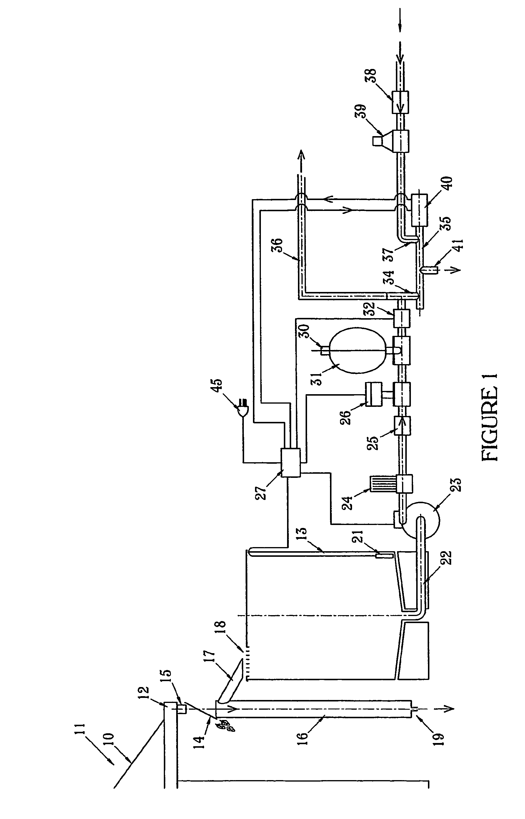
[0084]With reference to FIG. 1 there is shown a diagrammatic view of the first preferred embodiment. Rain water falls on the roof 10 of a building 11, flows into the gutter 12 and collects in the water tank 13. Coarse debris is prevented from entering the water tank 13 by an angled debris screen 14 which filters water flowing out of gutter spout 15. The water then enters a first flush system 16. The first flush system 16 takes the initial volume of water discharged from the roof 10 and incorporating particulate matter and any residue on the roof 10. In its simplest form the first flush system 16 includes a container that holds a volume of water and has a small discharge outlet 19. When the container has filled overflow passes through the spout 17 into the water tank 13 via the insect screen 18.

[0085]The water tank 13 has a water sensor 21 which has a single level device with hysteresis (or two or three level devices). Water is drawn from the water tank 13 via the outlet pipe 22 to t...


PUM


Abstract

A water supply system for supplying water to a building including a water tank (13) for collecting water from the roof (10) and gutters (12) of the building (11); a water level sensor means (21) for sensing the level of water in the water tank; a tank water system (22) for supplying water from the water tank (13); a water pump (23) for pumping water from the water tank (13) along the tank water system (22); a non-return valve (25) downstream of the pump in the tank water system; a pressure sensor means (26) for sensing water pressure of water within the tank water system, said pressure sensor means (26) is located downstream of the non-return valve (25); a mains water system for supplying mains water; a three port valve (35) having a first port (34) connected to the tank water system downstream from the pressure sensor means (26), a second port (37) connected to the mains water system and a third port (41) connected to the building's water reticulation system; wherein when the first (34) and third port (41) are open the second port (37) is closed and when the second (37) and third port (41) are open the first port (34) is closed; and a control means (27) for operatively receiving inputs from the water level sensor means (21), pressure sensor means (26) and mains electricity supply (45) and controlling the water pump (23) and the three port valve (35).

Description

FIELD OF INVENTION[0001]The present invention relates to a system for supplying water to a reticulation system from different sources. The present invention has particular but not exclusive application for a system using tank water and mains water supplies. Reference is made in the patent specification to tank water and mains water as water sources. This reference is by way of example only and other water sources or combinations of sources may be used.PRIOR ART[0002]Rainwater collected from the roofs of houses and buildings is commonly used in country areas. Rainwater is collected from the gutters and filtered through filtration systems before passing into a tank for storage. Water is drawn from the tank by the pump which supplies the water at pressure to the building's reticulation system.[0003]In most urban areas, water is supplied through a mains water system which provides treated water to houses and buildings connected by a mains water supply network. Mains water is supplied un...

Claims


Application Information

Patent Timeline
IPC IPC(8): E04D13/00E03B1/04E03B3/02E03B7/04
CPCE03B1/04E03B7/04E03B3/02E03B2001/047Y02A20/108Y10T137/7313Y10T137/2567Y10T137/8242Y10T137/6969Y10T137/86027
Inventor GRAYMOORE, RODNEY DOUGLASCAMERON, GREGORY DUNCAN
Owner URBAN RAINWATER SYST PTY LTD (AU)
Learn More