System for displaying graphics in a digital television receiver

a digital television and receiver technology, applied in the field of digital television, can solve the problems of complex circuits that must be provided, problems that may also occur, and no integrated chip set is available for such applications, and achieve the effect of avoiding the conversion of rgb signals or graphics data to a different frequency raster

Inactive Publication Date: 2006-06-27
MICRONAS
View PDF10 Cites 27 Cited by
  • Summary
  • Abstract
  • Description
  • Claims
  • Application Information

AI Technical Summary

Benefits of technology

[0007]Advantageously, conversion of the RGB signal or graphics data to a different frequency raster may be avoided. In addition, the method allows for essentially independent processing of the YUV signal and the RGB signal, or of the video data and graphics data, a feature which is typically required for special applications such as web applications with graphics data and simultaneous transfer of decoded video data for recording by an analog video recorder in the background.
[0008]An MPEG decoder may receive the data stream with the video data in digital format and generate from it the first YUV signal. The MPEG decoder may also generate the RGB signal and the mixing signal. The MPEG decoder may also provide the YUV signal at a CCIR656 connector in a 50 Hz frequency raster. A conventional converter may be connected to the CCIR656 connector for further processing, whereby the converter for example converts the first YUV signal in digital format to the second YUV signal in analog format. Specifically, the converter may convert the first YUV signal to the second YUV signal in the 100 Hz frequency raster. Such converters are inexpensive and readily available as standard components.
[0011]A circuit of this type may be easily made in the form of an integrated circuit or chip or chip set. Horizontal and vertical synchronization signals from the MPEG decoder may be fed to the video output unit, while horizontal and vertical synchronization signals from different sources (including those from the MPEG decoder) may be selectively fed through a multiplexer to the graphics output unit. One buffer memory each may be placed before the video output unit and the graphics output unit, respectively, each memory unit buffering the corresponding data retrieved from the central memory. A signal generator may be provided which generates horizontal and vertical synchronization signals and provides these to the multiplexer. Additional horizontal and vertical synchronization signals may be fed to the multiplexer from an external connector, for example, through a SCART connector. The video output unit may be operated at a first clock frequency, while the graphics output unit may be operated at a second clock frequency. This helps to achieve essentially independent processing of the graphics data and the video data.

Problems solved by technology

If, on the other hand, an application requires independent output of graphics and video data, complex circuits typically must be provided since, for example, in a 100 Hz television receiver, graphics data do not pass through an algorithm for raising the refresh rate to 100 Hz, as this would be superfluous.
Problems may also occur in applications, for example, in which decoded digital video data for recording are fed to an analog video recorder in the background.
Currently, no integrated chip set is available for such applications.

Method used


Image

  • System for displaying graphics in a digital television receiver
  • System for displaying graphics in a digital television receiver
  • System for displaying graphics in a digital television receiver

Examples


Embodiment Construction

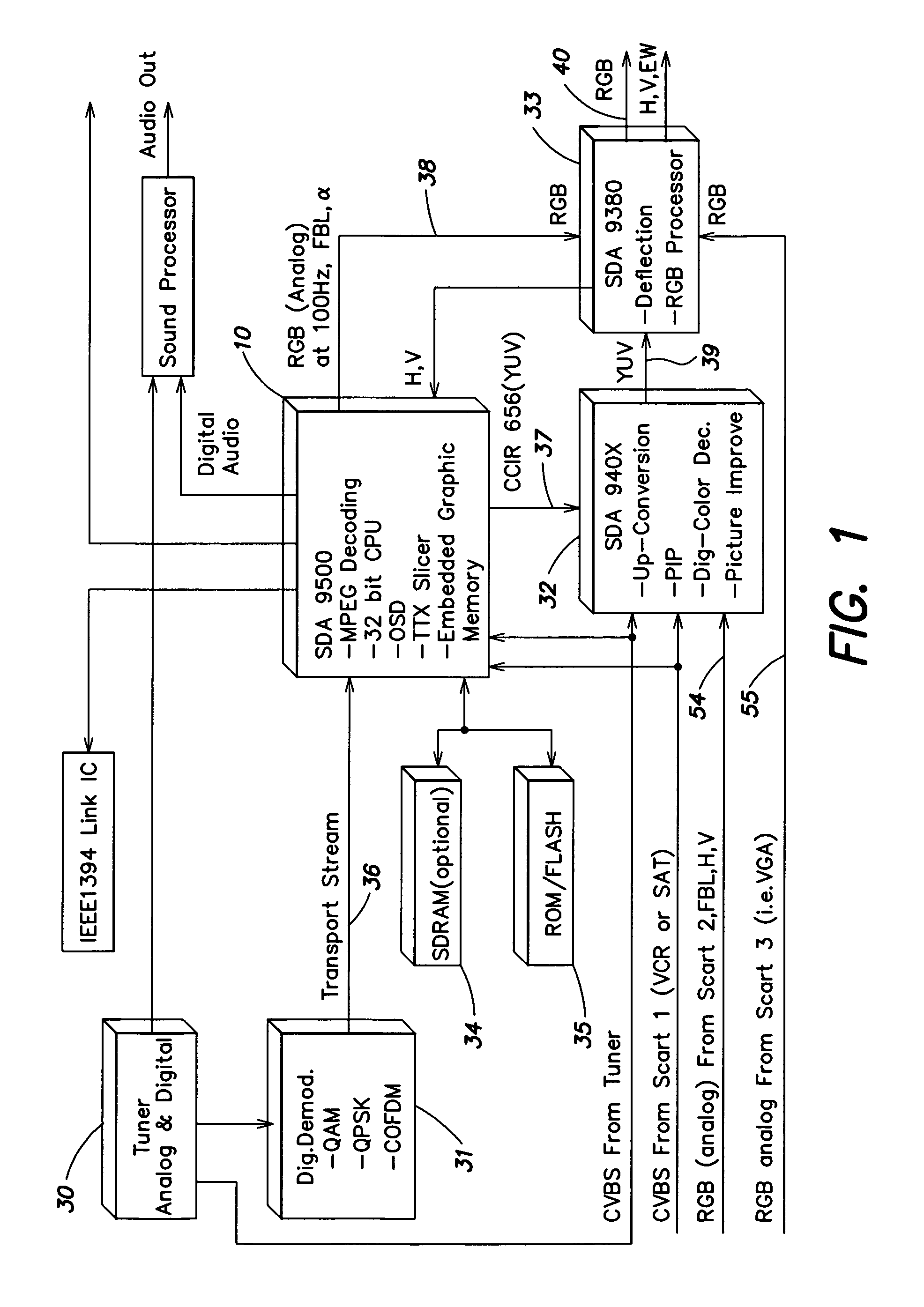
[0016]Referring to FIG. 1, a system for displaying graphics data and video data in a digital television receiver includes an MPEG decoder 10 (for example component SDA 9500) to which a digital data stream 36 is fed from a digital demodulator 31 which demodulates signals modulated by one of the modulation methods QAM, QPSK or COFDM. The digital demodulator 31 receives digital signals from an analog and digital tuner 30 which receives analog and / or digital television signals.

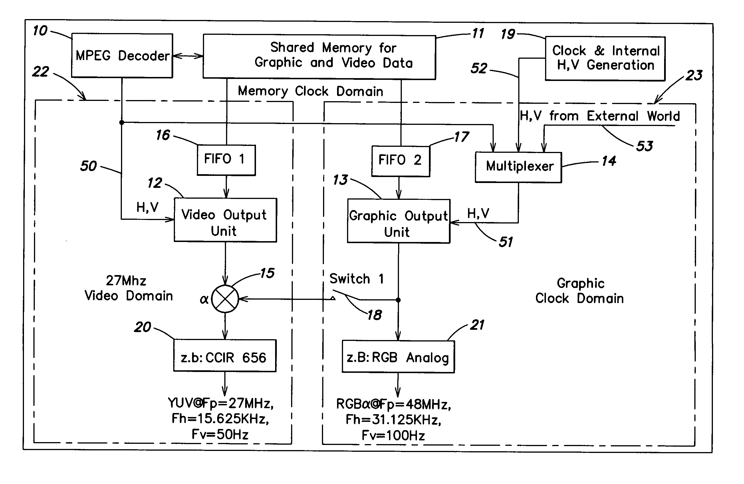
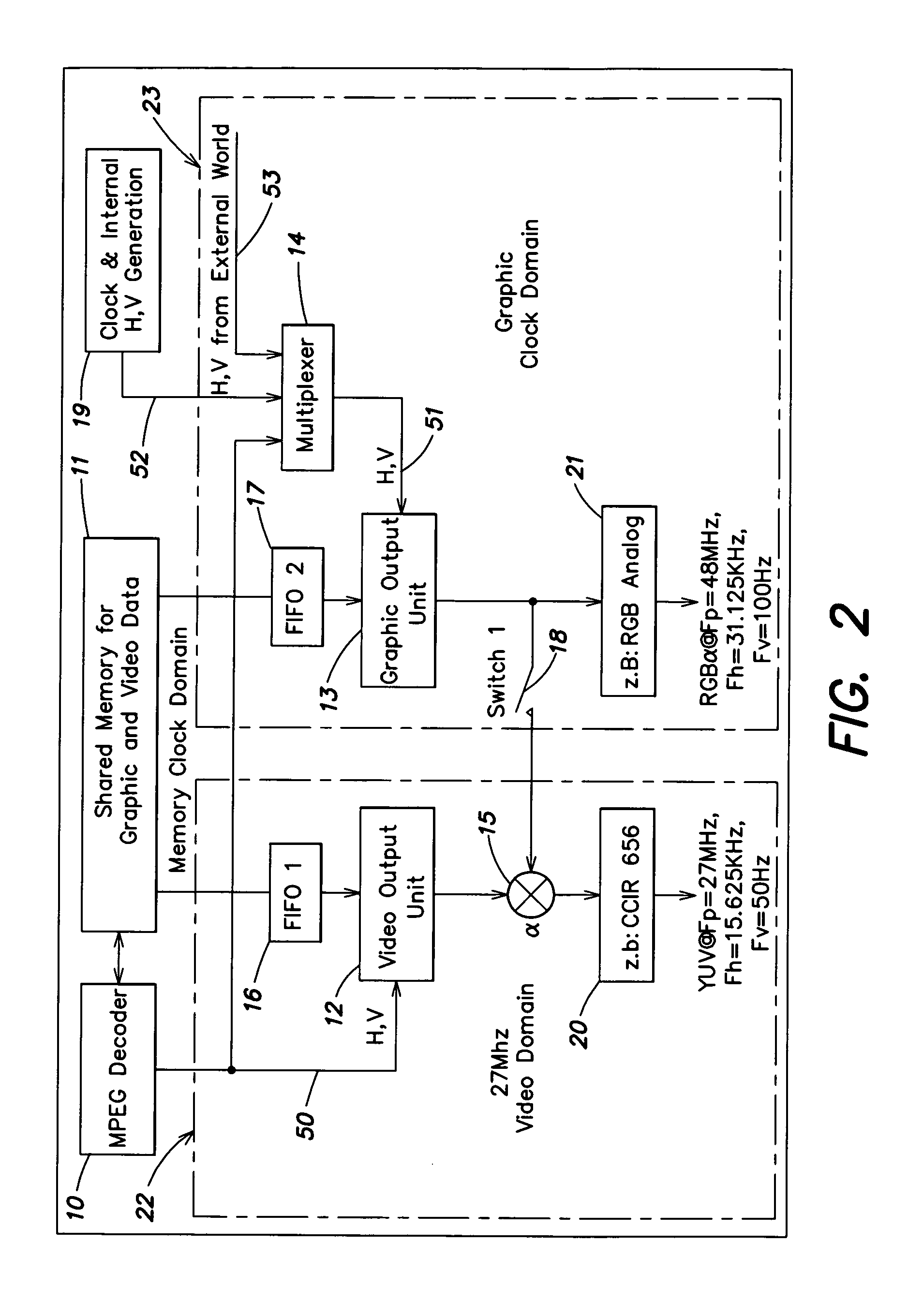
[0017]The MPEG decoder 10 decodes from the supplied data stream 36 a digital YUV signal 37 and provides this signal on the line 37 in 50 Hz format to a CCIR656 output of the decoder 10 in the form of digital data. The digital data typically include horizontal, vertical, and synchronization components, as well as a sampling rate of 27 MHz. The YUV signal on the line 37 in 50 Hz format represented by the digital data is up-converted by a converter 32 (for example component SDA 940x) to the 100 Hz format and is avail...


PUM


Abstract

A circuit for displaying graphics in a digital television receiver includes an MPEG decoder which has as input a video data stream in digital format, a central memory for storing decoded video data and graphics data, a video output unit and a graphics output unit to which video data and graphics data, respectively, are fed from the central memory, a mixer to which an output signal from the video output unit is fed, and a switch through which the output signal of the graphics output unit is selectively fed to the mixer. Horizontal and vertical synchronization signals from the MPEG decoder may be fed to the video output unit, while horizontal and vertical synchronization signals from various sources (including those from the MPEG decoder) may be selectively fed through a multiplexer to the graphics output unit. One buffer memory each may be placed before the video output unit and the graphics output unit, respectively, each memory unit buffering the corresponding data retrieved from the central memory. A signal generator may be provided which generates horizontal and vertical synchronization signals and provides these to the multiplexer. Additional horizontal and vertical synchronization signals may be fed to the multiplexer from an external connector. The video output unit may be operated at a first clock frequency, while the graphics output unit may be operated at a second clock frequency. This helps to achieve essentially independent processing of the graphics data and the video data. When the switch is closed, the first and second clock frequencies may be the same, and the same horizontal and vertical synchronization signals may then be sent to both the video output unit and the graphics output unit.

Description

PRIORITY INFORMATION[0001]This application claims priority from International patent application PCT / EP01 / 00131 filed Jan. 8, 2001 and German patent application DE 100 01 369.4 filed Jan. 14, 2000.BACKGROUND OF THE INVENTION[0002]The invention relates in general to the field of digital television, and in particular to a circuit for displaying graphics data along with video data in a digital television receiver.[0003]Highly-integrated chip sets including a digital TV decoder are available for digital television sets. The digital TV decoder typically has an MPEG video decoder, a unit for outputting decoded video data, and an on screen display (OSD) unit. The OSD unit has the function, for example, of displaying settings for the television set such as volume, color, contrast, brightness, etc. on the screen, but may be used to display any type of information such as data from the Internet. The OSD unit retrieves the graphics data in the same synchronization raster and pixel raster as th...

Claims


Application Information

Patent Timeline
Patent Type & Authority Patents(United States)
IPC IPC(8): H04N9/74H04N5/445H04N5/44H04N9/64
CPCH04N5/4401H04N5/44508H04N21/42653H04N7/0132H04N9/641H04N21/426H04N21/434
Inventor ENGLERT, ULRICH
Owner MICRONAS
Why Eureka
Try Eureka