System and method for generating analog transmission signals

a transmission signal and analog technology, applied in multiplex communication, semiconductor lasers, instruments, etc., can solve the problems of reducing the efficiency of rf signals, requiring smaller and lighter hardware than microwave counterparts, and significantly degrading performan

Inactive Publication Date: 2006-07-11
UNIV OF MARYLAND BALTIMORE COUNTY
View PDF7 Cites 82 Cited by
  • Summary
  • Abstract
  • Description
  • Claims
  • Application Information

AI Technical Summary

Benefits of technology

[0012]It is one object of the present invention to provide a system and method for generating analog transmission signals in a manner which overcomes the drawbacks of conventional transmission systems and methods.

Problems solved by technology

These links also require smaller and lighter their hardware than their microwave-counterparts.
For all their advantages, analog fiber-optic links have at least one drawback which significantly degrades their performance.
This drawback comes in the form of a large insertion loss, which results from an inefficient conversion of RF signals to amplitude-modulated optical signals.
This approach has proven undesirable because a balancing scheme must be used which increases the complexity of the system.
This approach is also deficient because an improved weakness of loss is required without introducing degradations to other figures of merit such as noise figures and spurious-free dynamic range (Drsp).
A transfer function of this type has proven undesirable for many communications applications involving analog links.
In view of the foregoing discussion, it is clear that there is a need for a system and method which generates analog transmission signals without realizing the drawbacks of conventional systems, and moreover which does so without realizing an insertion loss and without using a non-linear transfer function which has been shown to be unsuitable for use in many analog transmission applications.

Method used


Image

  • System and method for generating analog transmission signals
  • System and method for generating analog transmission signals
  • System and method for generating analog transmission signals

Examples


Embodiment Construction

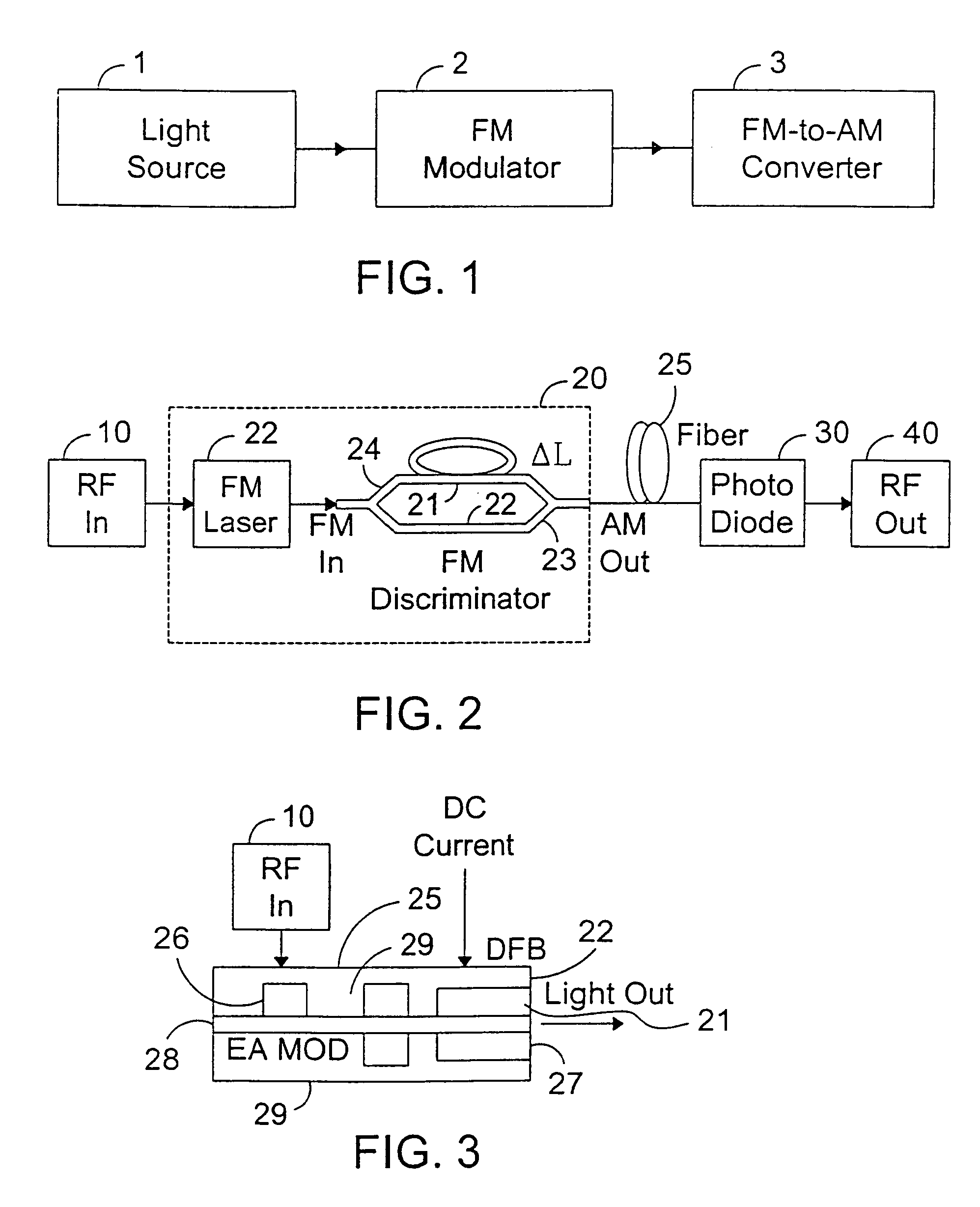
[0033]The present invention is, in one respect, a signal processor and method for generating modulated signals in an optical system. The present invention is, in another respect, a lightwave transmitter which may use the aforementioned signal processor for generating RF signals in a wireless communications system.

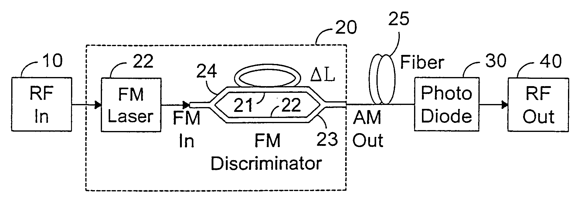
[0034]Referring to FIG. 1, a first embodiment of the signal processor of the present invention includes a light source 1, an FM modulator 2, and a linear FM-to-AM converter 3. The light source may be, for example, a semiconductor laser or a laser diode. The FM modulator modulates the frequency of a carrier signal with an input signal to produce an FM optical signal. Although the modulator is shown as being separate from the light source, those skilled in the art can appreciate that the modulator may be incorporated within the laser if desired. The linear FM-to-AM converter converts frequency variations in the optical signal output from the modulator into amplitude variation...


PUM


Abstract

An RF-lightwave transmitter performs successive conversions of an information-bearing input signal in order to generate an output signal suitable for transmission in a wireless communications system. The transmitter includes a high-efficiency FM laser connected to a FM discriminator. In operation, the laser converts an RF signal into a frequency-modulated optical signal, and the discriminator converts this signal into an amplitude-modulated optical signal. The discriminator performs its conversion using a high slope-efficiency linear transfer function which ensures that the AM optical signal varies in accordance with a desired operational performance. The transmitter also includes a photodiode which converts the AM signal output from the optical discriminator back into an RF signal for transmission. Experimental results demonstrated that a transmitter of this type is able to realize greater than 10 dB RF insertion gain at less than 0 dBm optical power, with a high spurious-free dynamic range and low noise. A signal processor embodied within the transmitter may be used in a purely optical communication systems or may be used for other types of RF-photonics applications such as those expected for use in next-generation systems.

Description

CROSS-REFERENCE TO RELATED APPLICATIONS[0001]The present application claims the benefit of provisional U.S. Patent Application Ser. No. 60 / 290,946, filed on May 14, 2001. The contents of this provisional application is incorporated herein by reference.BACKGROUND OF THE INVENTION[0002]1. Field of the Invention[0003]This invention generally relates to processing signals, and more particularly to a system and method for generating analog signals for transmission in a communications, a photonics-based system, or any other system which requires analog signal processing.[0004]2. Background of the Related Art[0005]In the broadest sense, a communications transmitter operates by modulating a carrier wave with an input (e.g,. voice) signal. The modulated signal is then transmitted at a predetermined frequency to a receiver, where it is detected and demodulated so that the original signal may be recovered. The recent demand for integrated voice and data services has given birth to new modulati...

Claims


Application Information

Patent Timeline
Patent Type & Authority Patents(United States)
IPC IPC(8): H04B10/00H04B10/04H01S5/026H01S5/062H03D9/00
CPCH01S5/0265H03D9/00H01S5/06226
Inventor CHOA, FOW-SEN
Owner UNIV OF MARYLAND BALTIMORE COUNTY
Why Eureka
Try Eureka