Hybrid DC electromagnetic contactor

a technology of electromagnetic contactor and hybrid dc, which is applied in the direction of circuit-breaking switches, emergency protective arrangements for limiting excess voltage/current, and pulse techniques, etc., can solve the problems of affecting the production cost of switches, and affecting the operation of switches. , to achieve the effect of reducing the size of leakage curren

Active Publication Date: 2006-07-18
LG IND SYST CO LTD
View PDF45 Cites 72 Cited by
  • Summary
  • Abstract
  • Description
  • Claims
  • Application Information

AI Technical Summary

Benefits of technology

[0036]In order to solve the above-mentioned problems, it is an object of the present invention to use a snubber circuit for protecting a semi

Problems solved by technology

Herein, when the switch is open and a current flows into the electrode, because arc is generated at a contact point due to energy stored in a stray inductance element of a line or a load or a power side, the contact point may be damaged.
However, because lots of heat is generated by an applied current due to a voltage lowering at both ends of the semiconductor switch, an additional heat sink or cooling fan is required, and accordingly they have been used only for special purposes.
However, the hybrid switch in FIG. 1 can be applied only when power is AC, if power is DC, because there is no method for extinguishing the triac 2 as a semiconductor switch device, a power semiconductor switching device having a forced extinguishing function such as an IGBT (insulated gate bipolar transistor), a MOS-FET (metal oxide semiconductor-field effect transistor) and a BJT (bipolar junction transistor) has to be used.
In that case, a current value flowing on the IGBT switch device is too big, and a p

Method used


Image

  • Hybrid DC electromagnetic contactor
  • Hybrid DC electromagnetic contactor
  • Hybrid DC electromagnetic contactor

Examples


Embodiment Construction

[0051]Hereinafter, the preferred embodiment of the present invention will be described in detail with reference to accompanying drawings.

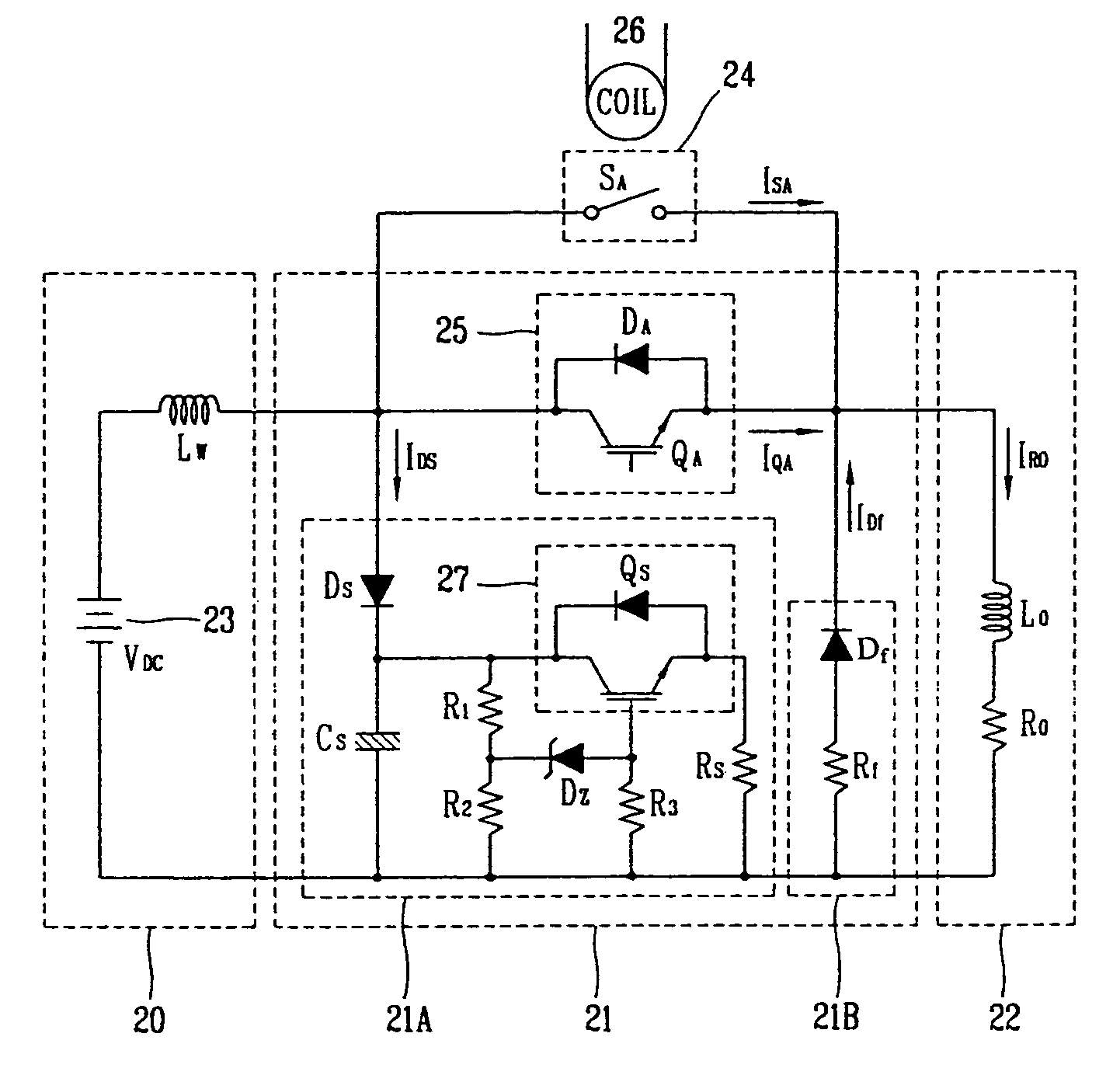
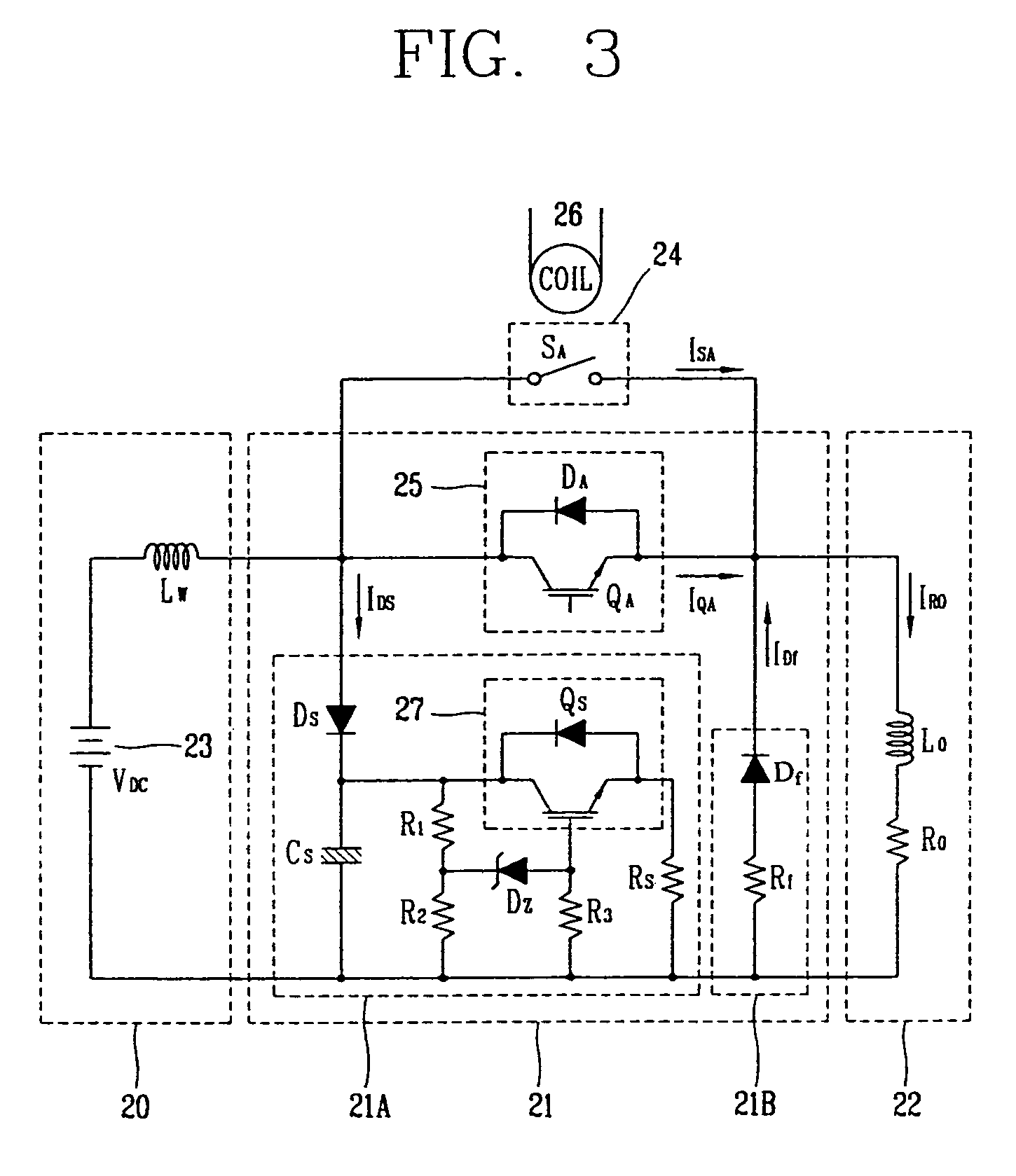
[0052]FIG. 3 is a circuit diagram illustrating a construction of a DC hybrid contactor in accordance with the present invention.

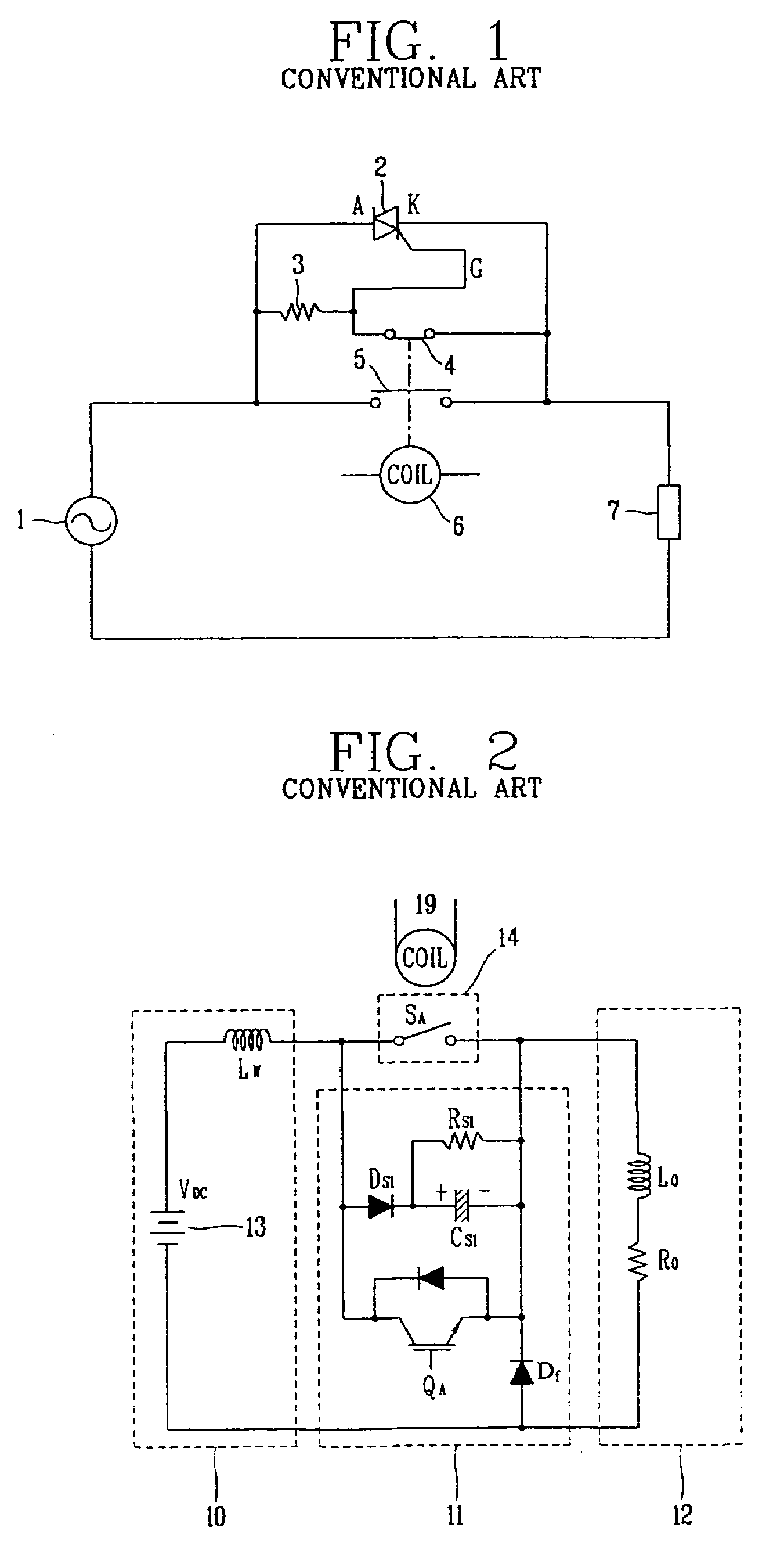
[0053]As depicted in FIG. 3, the DC hybrid contactor in accordance with the present invention includes a power unit 20 for supplying a certain power voltage; a main contact point 24 for providing a supply path of the power voltage by being switched according to the voltage apply to an operational coil 26; a first semiconductor switch 25 for providing a supply path of the power voltage according to a gate signal; a snubber circuit 21A for charging both ends voltage of the first semiconductor switch 25 in the turn-off of the first semiconductor switch 25, current being applied and discharged when the charged voltage is not less than a certain voltage; and a discharge current removing unit 21B for removing the discharge curre...


PUM


Abstract

In a hybrid DC electromagnetic contactor, by including a power unit for supplying a certain power voltage; a main contact point of a breaking switch for providing a supply path of the power voltage by being switched in accordance with a voltage apply to an operational coil; a switch for providing a supply path of the power voltage according to a gate signal; a snubber circuit for charging voltage at the both ends of the switch in turning off of the switch and being applied-discharged an electric current when the charged voltage is not less than a certain voltage; and a discharge current removing unit for removing the discharge current by providing a discharge current path to a load block in turning off of the switch, it is possible to minimize a size of leakage current when the main contact point and the semiconductor switch are turned off, and accordingly it can be practically used.

Description

BACKGROUND OF THE INVENTION[0001]1. Field of the Invention[0002]The present invention relates to a hybrid DC electromagnetic contactor, and in particular to a hybrid DC electromagnetic contactor capable of preventing arc occurrence in opening / closing of a hybrid-structured contactor and minimizing a leakage current by connecting a semiconductor switch to a mechanical contact switch in parallel.[0003]2. Description of the Prior Art[0004]In general, an electromagnetic contactor or an electromagnetic switch is used for connecting / cutting off power and load electrically.[0005]The contactor connects / cuts off separately fixed-installed two electrodes through a moving electrode, power of an electromagnet is used in connecting, and power of a spring is used in cutting off (separating). Herein, when the switch is open and a current flows into the electrode, because arc is generated at a contact point due to energy stored in a stray inductance element of a line or a load or a power side, the ...

Claims


Application Information

Patent Timeline
IPC IPC(8): H01H73/18H01H9/54H01H33/59H01H47/00H03K17/16H03K17/56
CPCH01H9/542H01H2009/544H01H33/596H01H47/00
Inventor CHUNG, YONG-HO
Owner LG IND SYST CO LTD
Why Eureka
Try Eureka