[0016]There is a need among biochemists and chemists for a syringe pushing device that is able to start and to stop instantly, and to move at a constant, defined velocity during its push. To achieve a precise time base for study of rates of chemical and
biochemical reactions in solution, especially rates of fast reactions, it is necessary to initiate and to terminate reactions quickly, reproducibly, and with high precision. The need is for a device which is able to push two or more syringes reliably, precisely, and reproducibly to enable quantitative kinetic study of rapid chemical and
biochemical reactions.
[0020]The present invention circumvents most of the difficulties inherent to the aforementioned
DC motor and
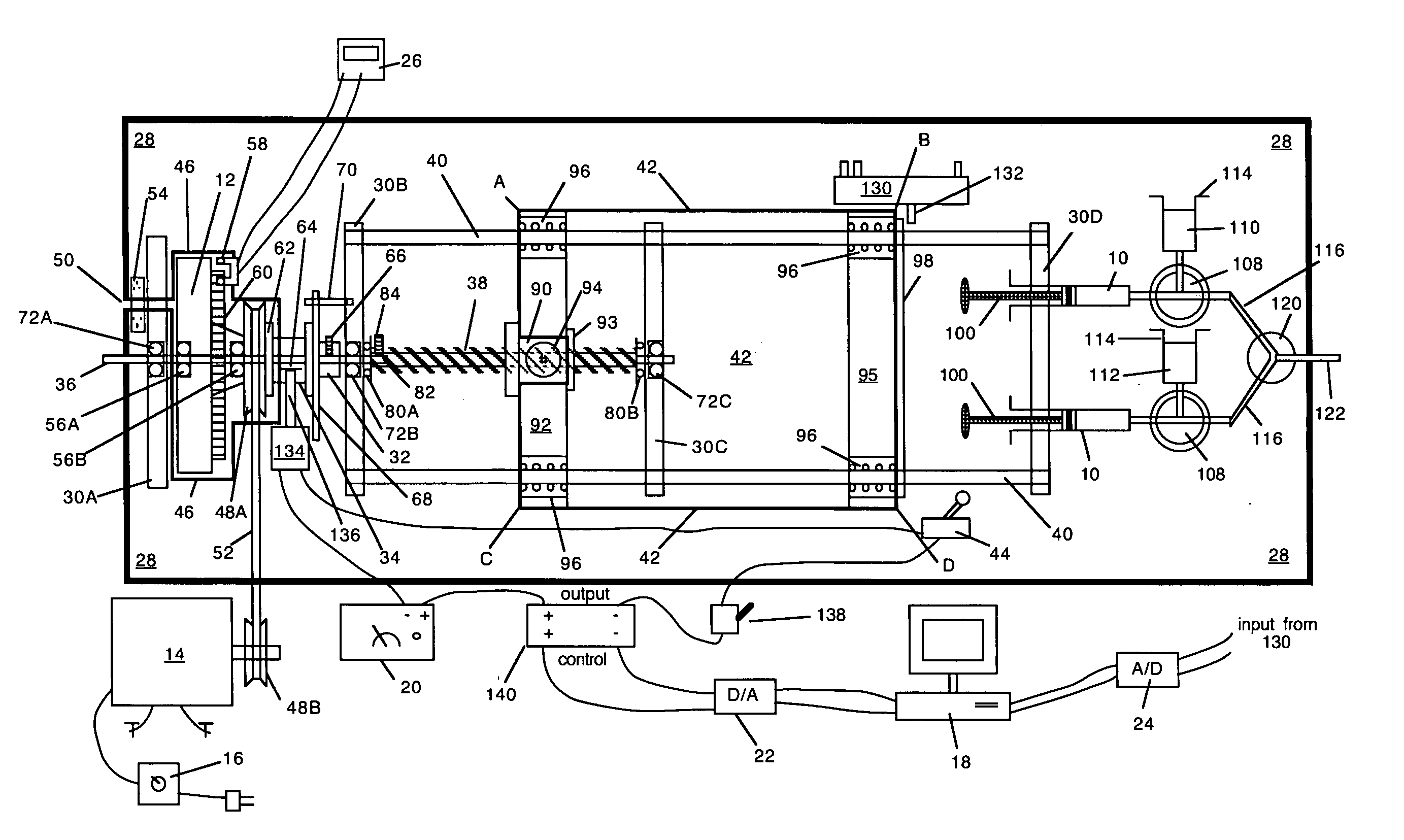
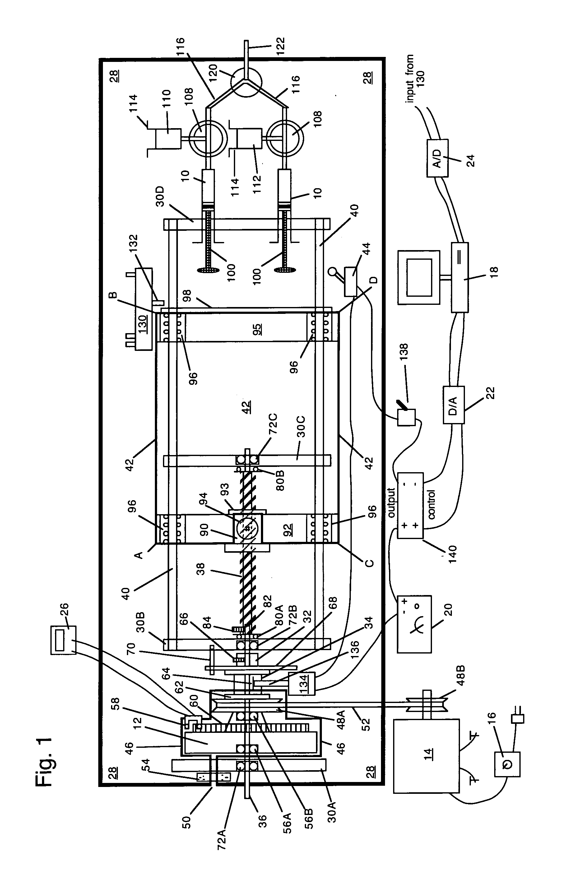
stepper motor designs, by employing a motor and flywheel that already are rotating at the desired final velocity needed for the push. Though the lead screw, push block, and syringes are initially at rest, their combined
inertia is negligible, and is about 1 / 2800th that of our
spinning aluminum flywheel. The wrap-spring clutch system engages fully, and accelerates the load from rest to full velocity, reproducibly within 3 msec, and this clutch disengages and decelerates the rotating lead screw back to rest within 1.5 msec. Between start and stop, the motion of the push block is of
constant velocity and of repeatable duration. The problems of stalling and inadequate power exhibited by the
stepper motor designs are eliminated by the use of a suitably large flywheel and motor. Ramped acceleration is not necessary with the present invention, because acceleration occurs within 3 msec, regardless of the load, and the period of acceleration is independent of the rotational velocity of the motor and flywheel. The present invention additionally has very
high torque, and is able to push against very high back pressures, which normally would cause a
stepper motor to stall.
[0021]The previously mentioned DC-motor, stepper-motor and
servo-motor designs have the
advantage that subsequent pushes can be of any desired velocity. The wrap-spring clutch system can be programmed easily for different durations and distances of push, and for any number, combination, and frequency of successive pushes; however different velocities of push necessitate varying the speed of the motor and flywheel, which is not necessarily a rapid process due to the inertia of the flywheel.
[0024]Though the unidirectionality and irreversibility inherent to the wrap spring clutch can be viewed as disadvantageous, irreversibility actually fulfills a critical role between pushes of the ram. Because of its irreversibility, the wrap spring clutch can maintain the rotational position of the stopped lead screw, and thus can hold the ram's stopped push block stationary between pushes, even against a
back pressure or a load. In fact, because of the combination of both engagement and
brake springs in the design of the Warner wrap spring clutch, the lead screw cannot be rotated either in a forward, or in a reverse, direction when the wrap spring clutch is disengaged. Thus both before and after a push of the wrap spring clutch syringe ram, the push block and the syringe(s) remain held firmly in their beginning and final positions because rotation of the lead screw is prevented by the immobilized output hub of the disengaged wrap spring clutch. Thus the single wrap spring clutch serves the functions of starting the load very rapidly, of moving the load precisely, of stopping the load very rapidly and precisely, and of holding the load stationary before and after each push. To fulfill these design requirements normally would necessitate, at minimum, a separate clutch and a separate
brake, plus some means to control and to coordinate their actions precisely and reproducibly; these requirements all are fulfilled completely, reproducibly, and efficiently, by the wrap spring clutch syringe ram.
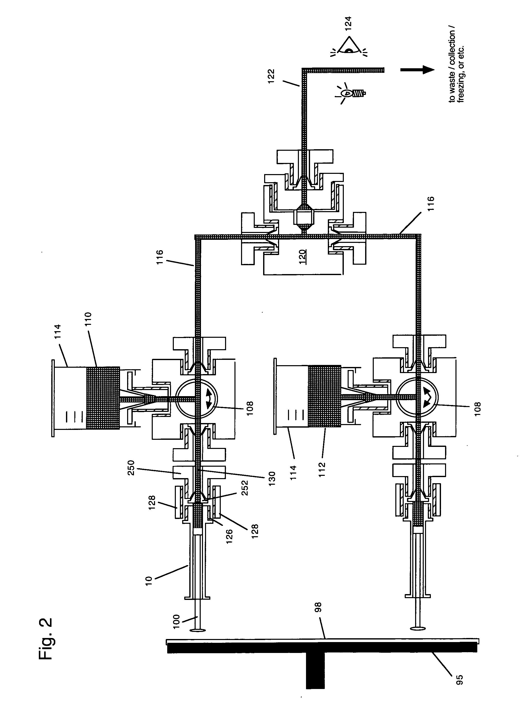
[0027]The
fluid output of each syringe is fed through a separate line to a
mixing chamber, where the flowing fluids expelled from two or more syringes meet and mix. Mixing chambers can be of various designs. We here present a mixer that employs a porous
frit immediately beyond the point of union of the flowing streams. The
frit assists to mix the flowing
reagent solutions rapidly, and in minimal volume, and thus enables rapid
initiation of reactions.

