Adjustment method and apparatus of optical system, and exposure apparatus

Inactive Publication Date: 2006-08-01
CANON KK
View PDF8 Cites 20 Cited by
  • Summary
  • Abstract
  • Description
  • Claims
  • Application Information

AI Technical Summary

Benefits of technology

[0016]A method of one aspect of the present invention for adjusting an optical system that has a multilayer mirror that includes a multilayer film includes the steps of measuring wave front aberration of the optical system, determining a condition to remove part of the multilayer film in the multilayer mirror so that the wave front aberration measured in the measuring step may reduce, and removing the part of the multilayer film in the multilayer mirror based on the condition determined by the determining step. The condition may define a removal area and/or a removal amount.
[0017]The method may further include the steps of calculating an adj

Problems solved by technology

However, the lithography using the ultraviolet light has the limit to satisfy the rapidly promoting fine processing of a semiconductor device, and a reduction projection optical system using extreme ultraviolet (“EUV”) light with a wavelength of 10 to 15 nm shorter than that of the ultraviolet has been developed to efficiently transfer a very fine circuit pattern of 0.1 μm or less.
Only polishing has a difficulty in

Method used


Image

  • Adjustment method and apparatus of optical system, and exposure apparatus
  • Adjustment method and apparatus of optical system, and exposure apparatus
  • Adjustment method and apparatus of optical system, and exposure apparatus

Examples


Example

First Embodiment

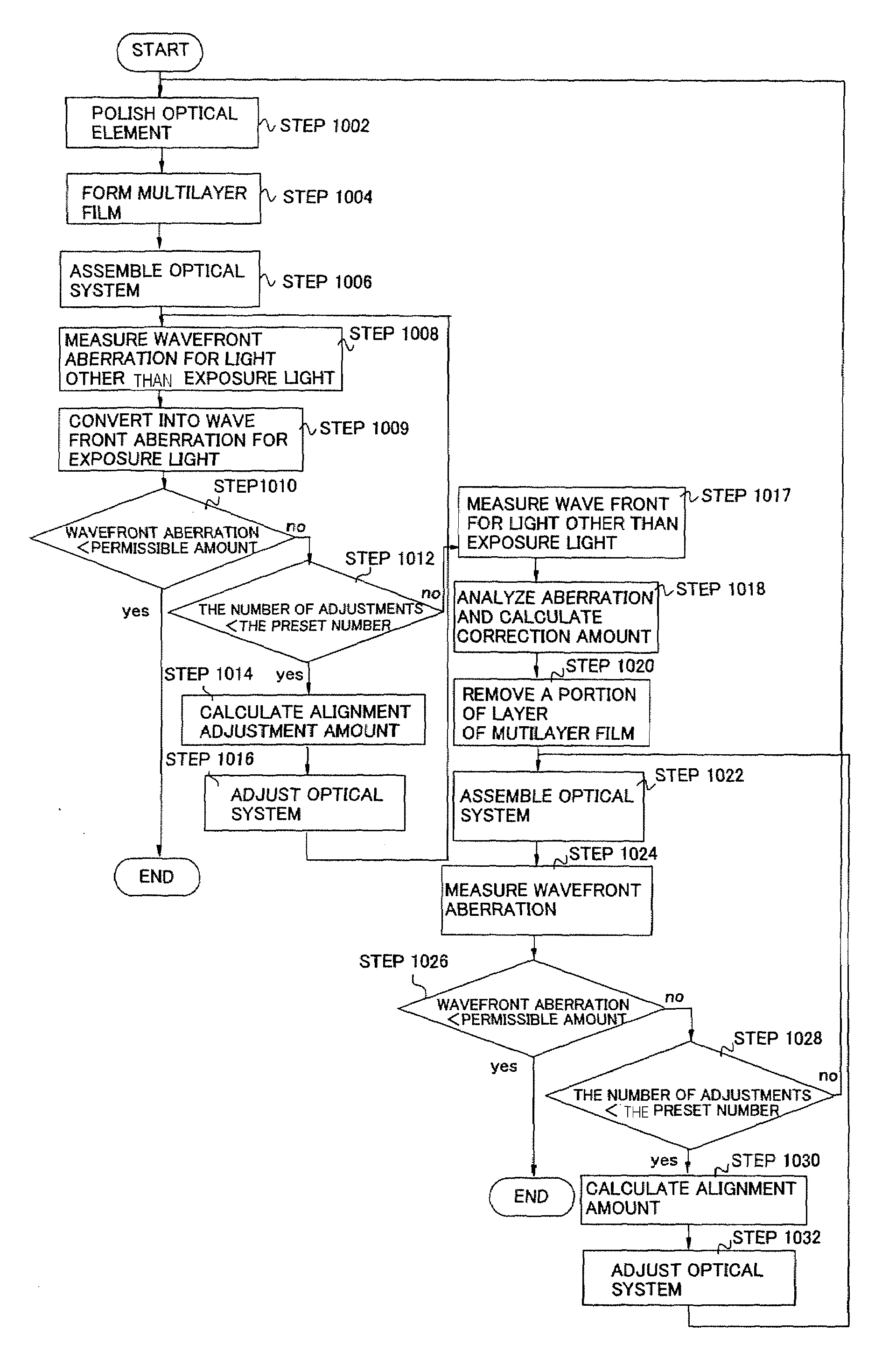
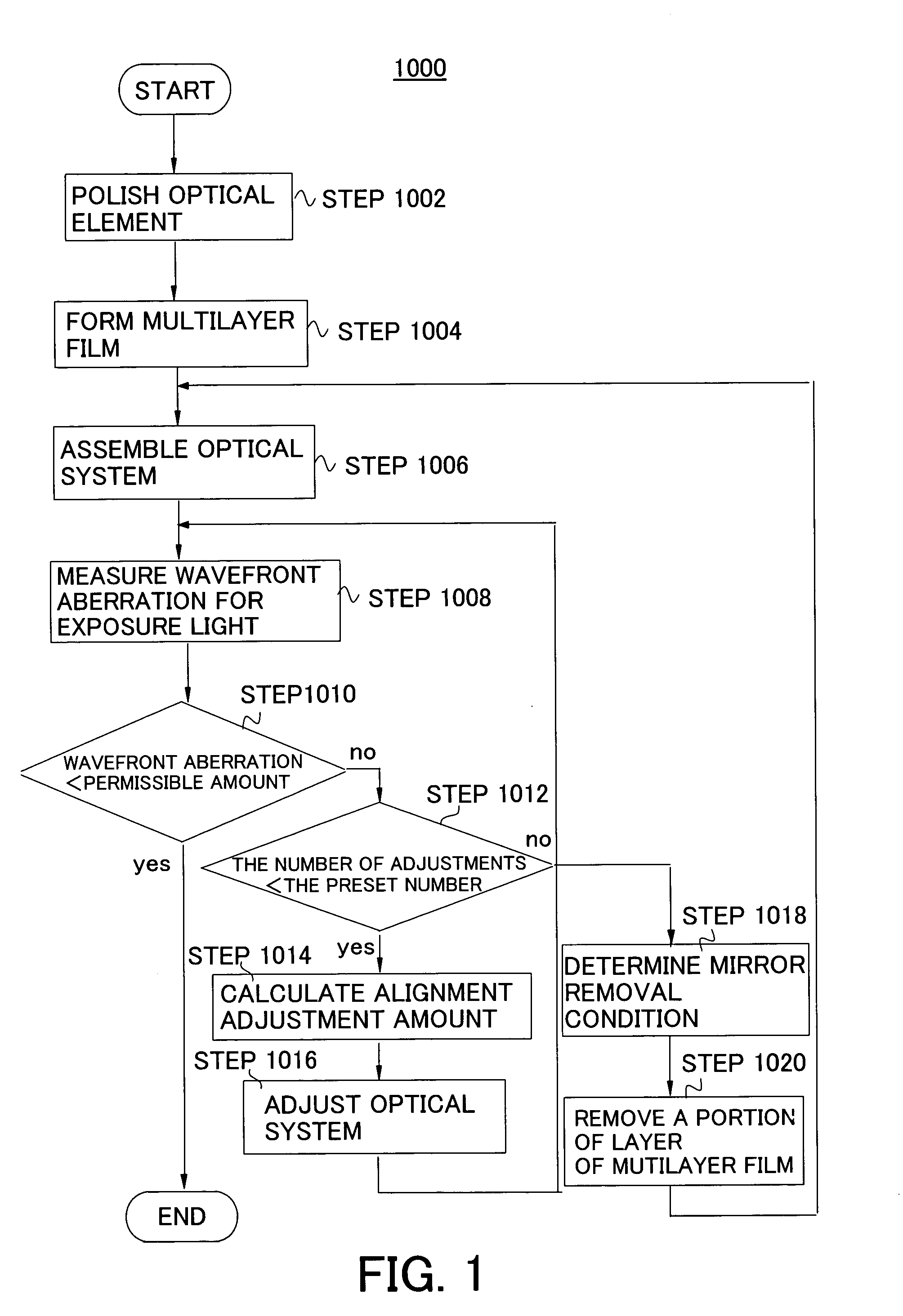
[0053]A description will be given of an inventive adjustment method 1000 that uses the above adjustment apparatus 100. FIG. 1 is a flowchart for explaining the inventive adjustment method. Here, a description will be given of an exemplary adjustment of the projection optical system including a Mo / Si multilayer mirror in an exposure apparatus.

[0054]As expressed by Equation 2, each Mo / Si multilayer mirror is polished with sufficient surface precision in the projection optical system (step 1002). A multilayer film is formed by alternately layering Mo and Si on a mirror surface that has been polished with sufficient surface precision (step 1004). For example, the entire mirror layers a multilayer film that a Mo layer has a thickness of about 2 nm and a Si layer has a thickness of about 5 nm.

[0055]Next, the multilayer mirror is assembled into a mirror barrel of the projection optical system (step 1006). The measurement part 110 measures the wave front aberration of the pr...

Example

Second Embodiment

[0062]In measuring wave front aberration of the projection optical system using ultraviolet light, visible light, and infrared light, it is difficult to measure the wave front at the area that has experienced coating milling with the wavelength of the ultraviolet light, visible light, and infrared light. The multilayer film in the area that has experienced coating milling includes such steps that wave front observed using the ultraviolet light, visible light, and infrared light greatly shifts unlike the observation of the wave front aberration of the EUV wavelength. Therefore, in measuring the wave front aberration using the ultraviolet light, visible light, and infrared light, it is difficult that the procedure is repeated from the step 1006 to the step 1020 for plural times of coating milling as discussed above.

[0063]Accordingly, the following method may be used to adjust the optical system. A description will now be given of an adjustment of an optical system for...

Example

Third Embodiment

[0071]In the first and second embodiments, the step 1008 uses the exposure light or the EUV light to measure the wave front aberration. The wave front measurement using the exposure wavelength often needs large facility, such as a synchrotron light source. On the other hand, given a relationship between the wave front measured by the exposure light and the wave front measured by the light, such as ultraviolet light, visible light, and infrared light, other than the exposure light, the wave front measurement using the light other than the exposure light provides information on the wave front measured by the exposure light, without requiring the large facility.

[0072]The relationship between the wave front measured by the exposure light and the wave front measured by the light other than the exposure light may be obtained from simulation, etc. Suppose, for example, an optical system having ideal imaging performance for the EUV light, and then the wave front aberration o...


PUM


Abstract

A method for adjusting an optical system that has a multilayer mirror that includes a multilayer film includes the steps of measuring wave front aberration of the optical system, determining a condition to remove part of the multilayer film in the multilayer mirror so that the wave front aberration measured in the measuring step may reduce, and removing the part of the multilayer film in the multilayer mirror based on the condition determined by the determining step.

Description

[0001]This application claims a benefit of priority based on Japanese Patent Application No. 2002-220389, filed on Jul. 29, 2002, which is hereby incorporated by reference herein in its entirety as if fully set forth herein.BACKGROUND OF THE INVENTION[0002]The present invention relates generally to an adjustment method and apparatus for adjusting an exposure apparatus that exposes an object, such as a single crystal substrate for a semiconductor wafer (plate or ball), and a glass plate (wafer) for a liquid crystal display (LCD). The present invention is particularly suitable, for example, for an exposure apparatus that uses ultraviolet light and extreme ultraviolet (“EUV”) light as a light source for exposure.[0003]A reduction projection exposure apparatus has been conventionally employed which uses a projection optical system to project a circuit pattern formed on a mask (reticle) onto a wafer, etc. to transfer the circuit pattern, in manufacturing such a fine semiconductor device ...

Claims


Application Information

Patent Timeline
IPC IPC(8): G03B21/00G01B11/24H01L21/027G02B5/08G02B17/06G03F7/20G21K1/06
CPCB82Y10/00G02B5/0891G02B17/0663G21K1/062G03F7/70316G03F7/706G21K1/06G03F7/70258H01L21/027
Inventor MASAKI, FUMITAROMIYAKE, AKIRA
Owner CANON KK
Why Eureka
Try Eureka