System and method for transmitting control information over an AC power network

a technology of control information and power network, applied in transmission systems, modulated carrier systems, electromechanical clocks, etc., can solve problems such as difficulty in bi-directional data network use of power distribution systems, power noise eventually swamps even the most sophisticated modulation schemes, and blockage of upstream message propagation

Inactive Publication Date: 2006-08-01
ADS ENTERPRISES NZ
View PDF3 Cites 174 Cited by
  • Summary
  • Abstract
  • Description
  • Claims
  • Application Information

AI Technical Summary

Problems solved by technology

This is primarily due to cumulative noise generated by all devices attached to the power network.
Such electrical noise eventually swamps even the most sophisticated modulation schemes.
As a result of this design characteristic, upstream message propagation is blocked.
This makes the power distribution system difficult and expensive to use for bi-directional data networks such as Internet traffic.
By offering a reduced tariff the electricity companies get to manage this load in times of emergency but can not easily isolate a single device or small customer.
This results in ripple control being useless as a general messaging system with its total throughput measured in bits per hour.
The receivers are also bulky and expensive and not suited to the kind of automation that a customer would use.
These devices can not operate continuously for prolonged periods due to overheating and have short life expectancies for a very expensive and functionally crucial device to the power company if they are used frequently.
The on / off duty cycle of existing ripple control systems is a significant design issue.
Historically overheating and power consumption are the major factors limiting the equipment's use.
Impedance mismatches and even the small voltage fluctuations at the high operating voltages of solid state ripple control result in the matching equipment overheating (low voltage) or needing to be rated at a high power to provide power in parallel with the main power distribution network (high voltage).
Looking upstream the ‘reluctance’ of the network is extremely high.
This requires expensive or elaborate devices or the co-location of data networking equipment to propagate the signal back to the central transmission point via other means such as radio, telephone line, fiber optic or such data line.
The problems continue downstream in distributing an IP type Internet network using the Power Network.
Older buildings don't tend to have existing phone wiring in every room, and using an RF type link is expensive and restrictive based on building construction materials.
This other than complexity and cost also suffers limited distribution distance due to attenuation and interference.
It is unidirectional and broadcast in nature unlike that used within power system based IP based (Internet) networks that have been tried to date.
This also reduces the power rating of the injection device or any matching transformer connected to the power distribution network.

Method used


Image

  • System and method for transmitting control information over an AC power network
  • System and method for transmitting control information over an AC power network
  • System and method for transmitting control information over an AC power network

Examples


Embodiment Construction

[0092]For the purposes of promoting an understanding of the principles of the present inventions, reference will now be made to the embodiments, or examples, illustrated in the drawings and specific language will be used to describe the same. It will nevertheless be understood that no limitation of the scope of the invention is thereby intended. Any alterations and further modifications in the described embodiments, and any further applications of the principles of the inventions as described herein are contemplated as would normally occur to one skilled in the art to which the invention relates.

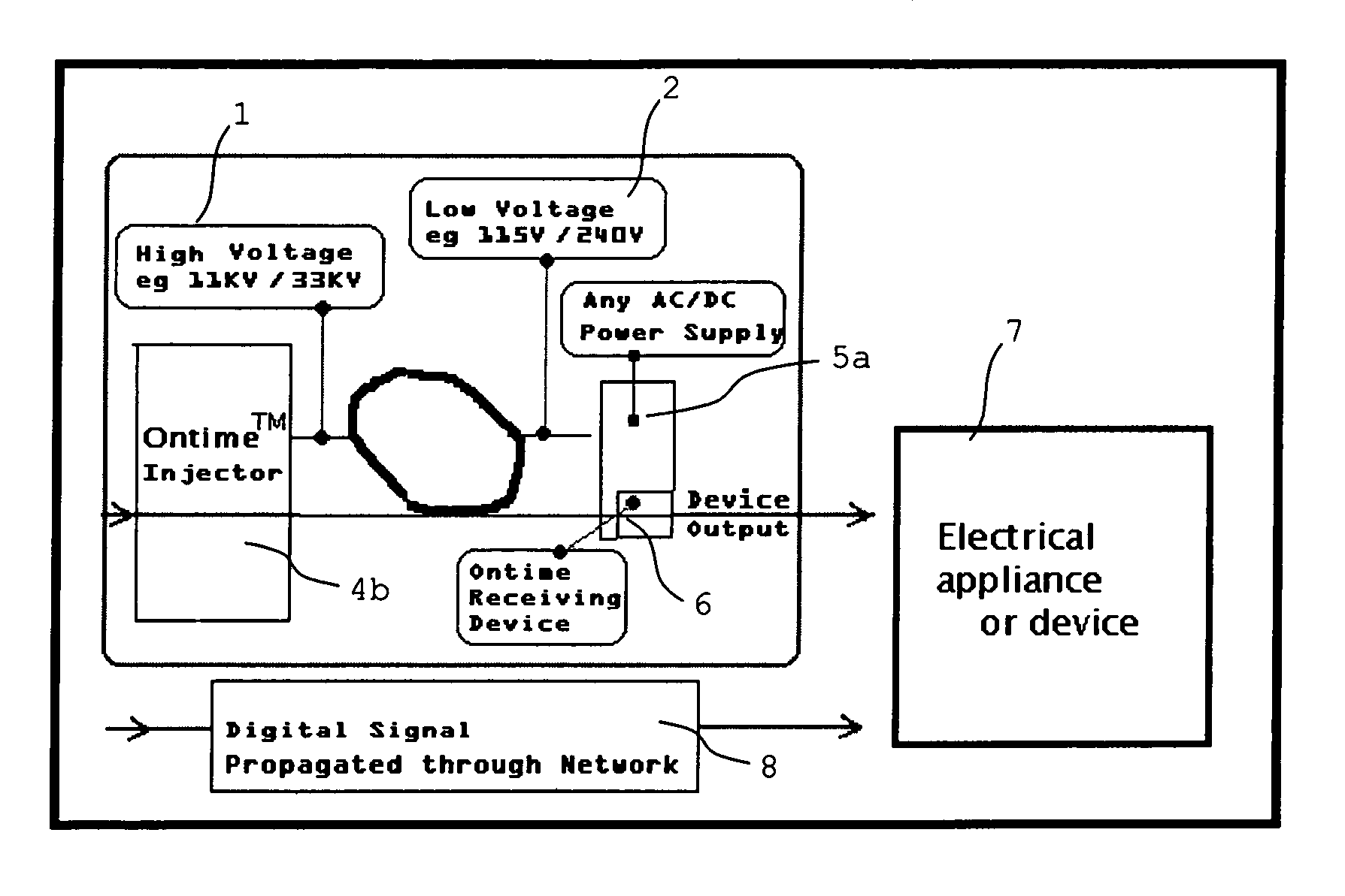
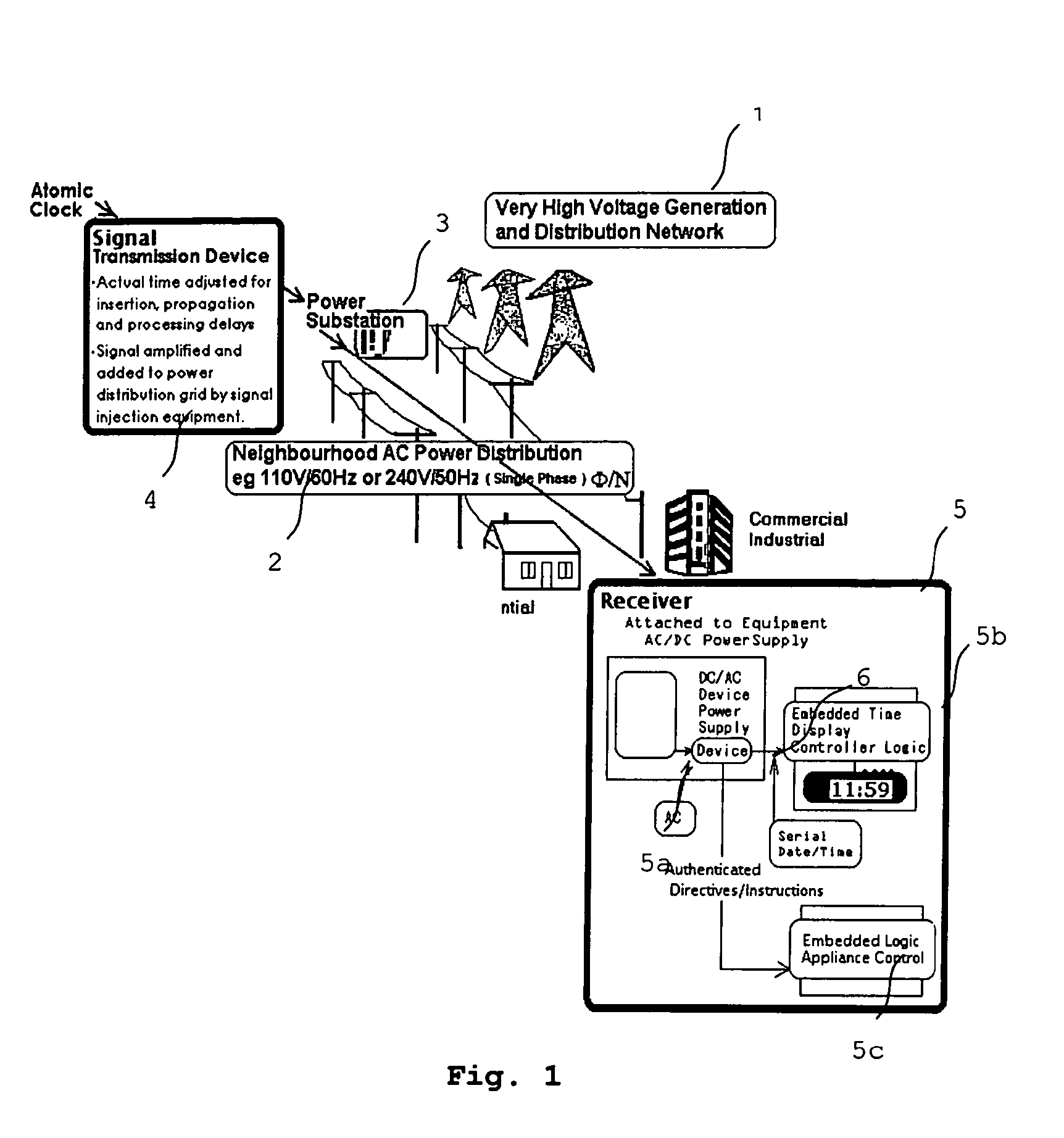
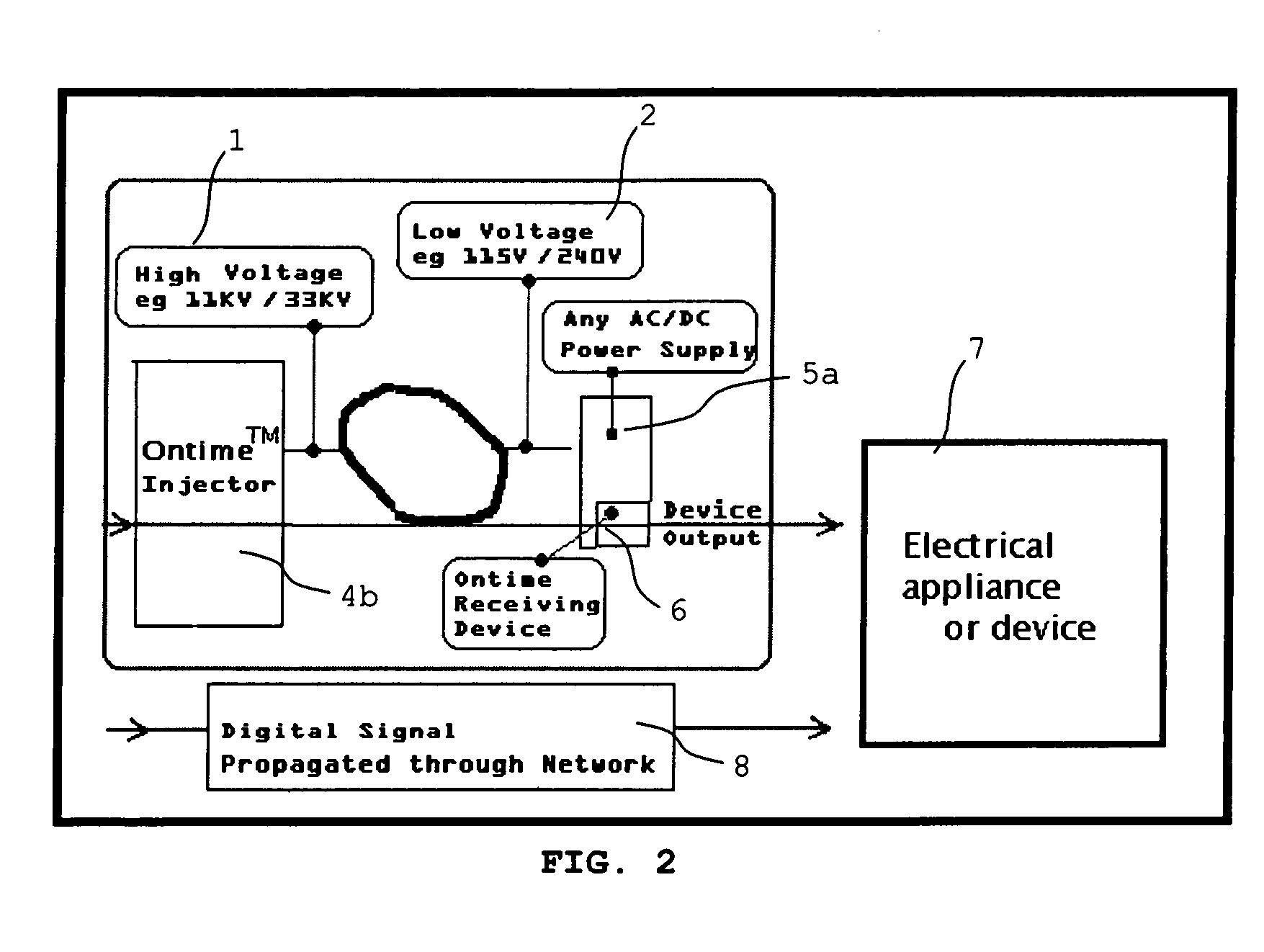
[0093]OnTime™ describes a ‘Method’ for continuously transmitting a Date and Time synchronisation signal to clocks and electronic appliances using or displaying time.

[0094]FIG. 1 shows an arbitrary AC Power reticulation network, comprising a very high voltage generation and distribution network 1 and a neighborhood AC power distribution 2, which are connected via a power substation 3. OnTime™...


PUM


Abstract

Disclosed is a transmission system for transmitting digital information via a power supply network. In one embodiment, there is a transmission device which comprises a generator for generating a simulated digital wave-form carrying the digital information to be transmitted, and a high-voltage injector to inject the generated simulated digital wave-form carrying the digital information into the power supply network. A receiving device is also disclosed, which comprises an analog detector for detecting predetermined harmonic frequencies of a signal frequency, and a logic device to output a logic signal corresponding to the output of the analog detector as said digital information.

Description

CROSS-REFERENCE[0001]This application claims benefit of the filing date of European Patent Application Number 03026995.5, entitled, “System for Sending Date and Time and Control Messages to Clocks or Electrical Appliances Connected to an Electricity Reticulation Network” filed on Nov. 26, 2003.TECHNICAL FIELD[0002]The present invention relates to a system for transmitting digital information via a power supply network and using this information to control and / or enhance electronic devices.BACKGROUND INFORMATION[0003]Electricity at 60 Hz is normally distributed by a 3 phase 11 KV or 33 KV network distribution network. Its final step is to pass through neighborhood transformers which drop the voltage down to typically either a nominal 110VΦ / N for use by the networks retail customers.[0004]The AC Power distribution Network looking downstream behaves as a very low pass filter, i.e. it attenuates frequencies sharply much above 100 Hz and by 1400 Hz transmission at regulated voltages is a...

Claims


Application Information

Patent Timeline
Patent Type & Authority Patents(United States)
IPC IPC(8): G05B11/01H04L27/00H04B3/00H04B3/54H04B3/56H04Q1/00
CPCH04B3/54H04B3/56H04B2203/5458
Inventor HAINES, ANTONY VINCENT
Owner ADS ENTERPRISES NZ
Why Eureka
Try Eureka