System using a levitating, rotating pumping or mixing element and related methods

Inactive Publication Date: 2006-08-08
PALL TECH UK
View PDF69 Cites 69 Cited by
  • Summary
  • Abstract
  • Description
  • Claims
  • Application Information

AI Technical Summary

Benefits of technology

[0044]In accordance with an eighteenth aspect of the invention, a system for pumping or mixing a fluid is disclosed. The system comprises a vessel for holding the fluid, the vessel having a cavity formed in at least one side thereof; a magnetic pumping or mixing element positioned in the vessel at a position concentric with the cavity and including first and second arrays of alternating polarity levitation magnets; at least two spaced arrays of superconducting elements positioned in or adjacent to the cavity in juxtaposition to the first and second a

Problems solved by technology

One significant limitation or shortcoming of such an arrangement is the danger of contamination or leakage during mixing.
This opening provides an opportunity for bacteria or other contaminants to enter, which of course can lead to the degradation of the product.
A corresponding danger of environmental contamination exists in applications involving hazardous or toxic fluids, or suspensions of pathogenic organisms, since dynamic seals or bearings are prone to leakage.
Cleanup and sterilization are also made difficult by the dynamic bearings or seals, since these structures typically include folds and crevices that are difficult to reach.
Recently, there has also been an extraordinary increase in the use of biosynthetic pathways in the production of pharmaceutical materials, but problems plague those involved in this rapidly advancing industry.
The primary problem is that suspensions of genetically altered bacterial cells frequently used to produce protein pharmaceuticals (insulin is a well-known example) require gentle mixing to circulate nutrients.
If overly vigorous mixing or contact between the impeller and the vessel wall occurs, the resultant forces and shear stresses may damage or destroy a significant fraction of the cells, as well as protein molecules that are sensitive to shear stresses.
This not only reduces the beneficial yield of the process, but also creates deleterious debris in the fluid suspension that requires further processing to remove.
However, several well-recognized drawbacks are associated with this mixing technology, making it unacceptable for use in many applications.
This of course generates substantial friction at the interface between the bar and the bottom wall of the vessel.
This uncontrolled friction generates unwanted heat and may also introduce an undesirable shear stress in the fluid.
Consequently, fragile biological molecules, such as proteins and living cells that are highly sensitive to temperature and shear stress, are easily damaged during the mixing process, and the resultant debris may contaminate the product.
Moreover, the magnetic bar stirrer may not generate the level of circulation provided by an impeller, and thus cannot be scaled up to provide effective mixing throughout the entire volume of large agitation tanks of the type preferred in commercial production operations.
As described above, the high torque generated can drive the impeller into the walls of the vessel creating significant friction.
Of course, high stresses at the interfaces between the ball bearings and the vessel wall or impeller result in a grinding of the mixing proteins and living cells, and loss of yield.
Further, the bearings may be sensitive to corrosive reactions

Method used


Image

  • System using a levitating, rotating pumping or mixing element and related methods
  • System using a levitating, rotating pumping or mixing element and related methods
  • System using a levitating, rotating pumping or mixing element and related methods

Examples


first embodiment

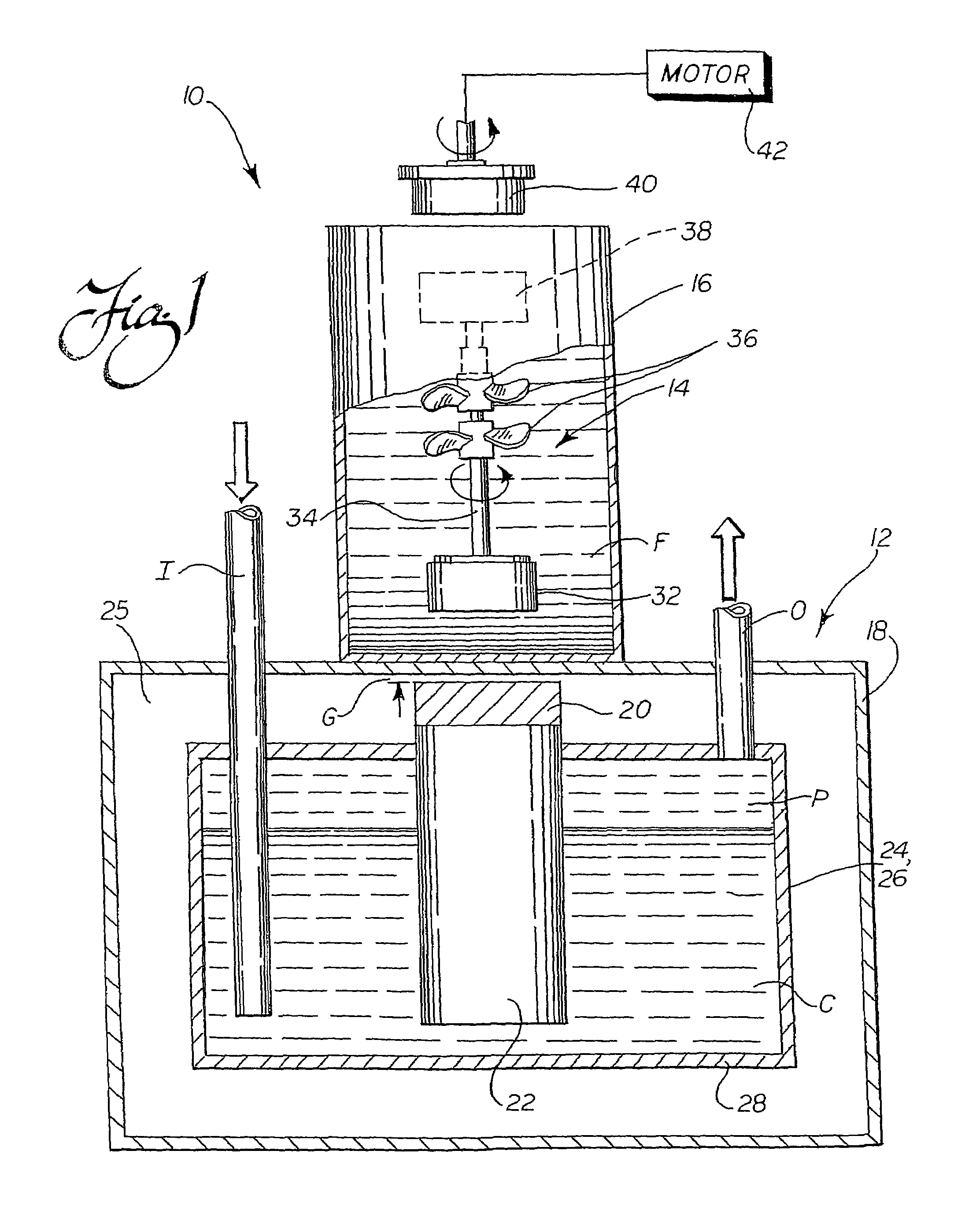
[0101]As should be appreciated from viewing FIG. 1, and as briefly noted in the foregoing description, the combination of the outer wall 18 and the inner cooling chamber 26 in this first embodiment defines the chamber 25 around the superconducting element 20. Preferably, this chamber 25 is evacuated to minimize heat transfer from the cooling chamber walls 28 and the superconducting element 20 to the outer wall 18 of the cryostat 12. The evacuation pressure is preferably at least 10−3 torr, and most preferably on the order of 10−5 torr, but of course may vary depending upon the requirements of a particular application. The important factor is that thermal transfer from the cooling source 24, which in this case is the cooling chamber 26 holding a cryogen C, and the superconducting element 20 to the outer wall 18 is minimized to avoid cooling the vessel 16 or fluid F held therein. Although a vacuum chamber 25 is proposed as one preferred manner of minimizing this thermal transfer, the ...
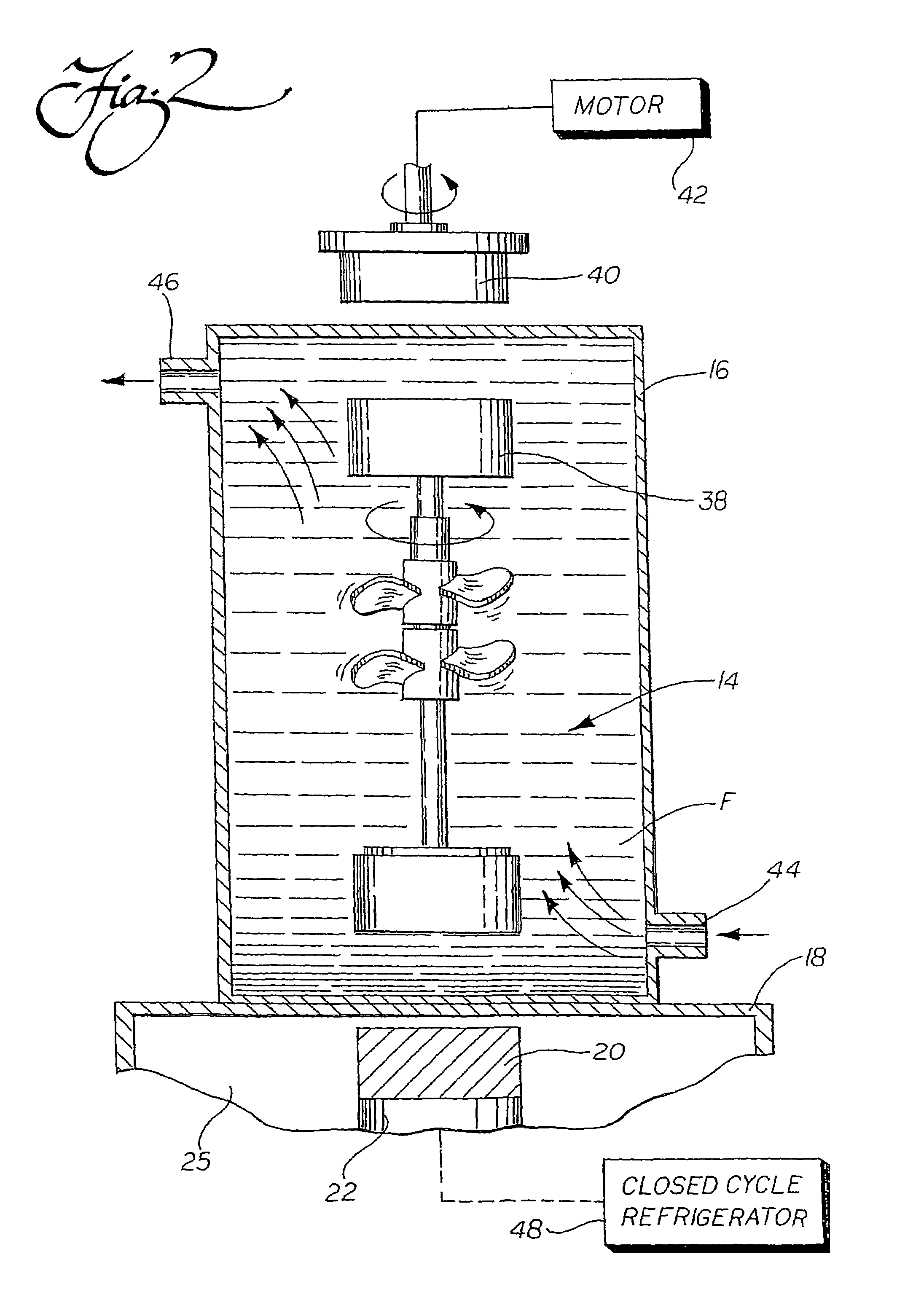
second embodiment

[0110]In accordance with another of the many important aspects of the present system 10, the absence of a mixing rod or other mechanical stirrer extending through a wall of the vessel 16 also allows for placement of the pumping or mixing element 14 at an off-axis position, as shown in FIG. 3. Specifically, the superconducting element 20, pumping or mixing element 14, and drive magnet 40 are all axially aligned away from the vertical center axis of the vessel 16. One particular advantage of using this approach is that the pumping or mixing element 14 may be rotated at a very low speed while the vessel 16 is also rotated about its center axis. This advantageously ensures that gentle, yet thorough mixing, is achieved, which is particularly advantageous for use with fluids that are sensitive to shear stress. As should be appreciated, this arrangement can be used both whether the vessel 16 is completely sealed, provided with an inlet 44 and an outlet 46 for pumping as shown in FIG. 2, or...
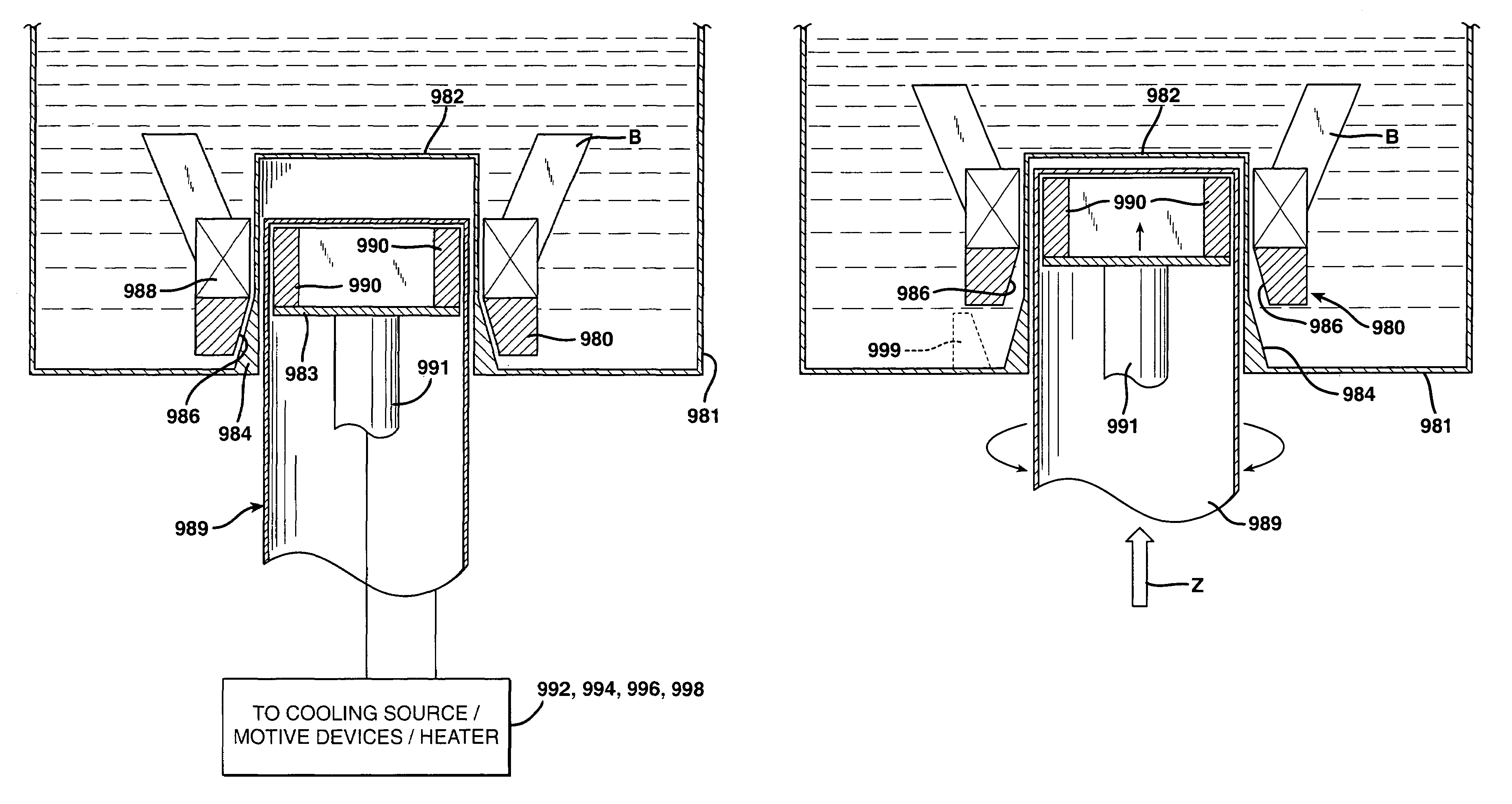
third embodiment

[0133]In accordance with yet another aspect of the present invention, a third version of a pumping or mixing system 200 is disclosed. In this third embodiment, which is illustrated in FIGS. 9, 9a, 9b, and 10, the forces for driving and levitating the pumping or mixing element 204 are supplied from the same side of a fluid vessel 202 (which is shown as an open-top container, but as described above, could be a sealed container, a pumping chamber or head, a flexible bag, a pipe, or the like). In this system 200, the pumping or mixing element 204 actually includes two magnetic subsystems: a first one that serves to levitate the pumping or mixing element 204, which includes a first magnet 206, preferably in the form of a ring, and a second magnetic subsystem that includes at least two alternating polarity driven magnets 208a, 208b, preferably positioned inside of the first, ring-shaped magnet 206, to transmit driving torque to the pumping or mixing element (see FIGS. 9a and 9b).

[0134]FIG...


PUM


Abstract

A system for pumping or mixing a fluid using a levitating, rotating pumping or mixing element and various other components for use in a pumping or mixing system are disclosed. The pumping or mixing element is placed in a fluid-containing vessel in close proximity to a superconducting element. A cooling source thermally linked to the superconducting element provides the necessary cooling to induce levitation in the pumping or mixing element. The superconducting element may be thermally isolated, such that the pumping or mixing element, the vessel, and any fluid contained therein are not exposed to the cold temperatures required to produce the desired superconductive effects and the resulting levitation. By using means external to the vessel to rotate and/or stabilize the pumping or mixing element levitating in the fluid, including possibly rotating the superconducting element itself or moving it relative to the vessel, the desired effective pumping or mixing action may be provided.

Description

[0001]This application claims the benefit of the following U.S. Provisional Patent Applications: (1) Ser. No. 60 / 239,187, filed Oct. 9, 2000, entitled “Pumping or Mixing System Using a Levitating Magnetic Bearing”; (2) Ser. No. 60 / 282,927, filed Apr. 10, 2001, entitled “Systems Using a Levitating, Rotating Pumping or Mixing Element and Related Methods”; and (3) Ser. No. 60 / 318,579, filed Sep. 11, 2001, entitled “Systems for Levitating and Rotating a Pumping or Mixing Element Including Assist Magnets.”TECHNICAL FIELD[0002]The present invention relates generally to the levitation of magnets using superconductivity and, more particularly, to a system, related components, and related method for pumping or mixing fluids using a rotatable magnetic element levitated in a vessel by a superconducting element.BACKGROUND OF THE INVENTION[0003]Most pharmaceutical solutions and suspensions manufactured on an industrial scale require highly controlled, thorough mixing to achieve a satisfactory yi...

Claims


Application Information

Patent Timeline
IPC IPC(8): B01F13/08F04B17/00H01L39/00B01F25/60B01F27/91
CPCB01F7/00908B01F7/16B01F13/0818B01F13/0827F16C37/005B01F13/0863B01F15/00831B01F15/0085F16C32/0438B01F13/0845B01F7/02B01F2215/0032B01F27/50B01F27/60B01F27/80B01F33/4532B01F33/4534B01F33/4535B01F33/453B01F33/452B01F35/513B01F35/51B01F2101/22B01F31/70B01F31/441B01F31/443
Inventor TERENTIEV, ALEXANDRE N.
Owner PALL TECH UK
Why Eureka
Try Eureka