
Perfusion balloon angioplasty catheter

Inactive Publication Date: 2006-08-08
BOSTON SCI SCIMED INC
View PDF47 Cites 20 Cited by
  • Summary
  • Abstract
  • Description
  • Claims
  • Application Information

AI Technical Summary

Benefits of technology

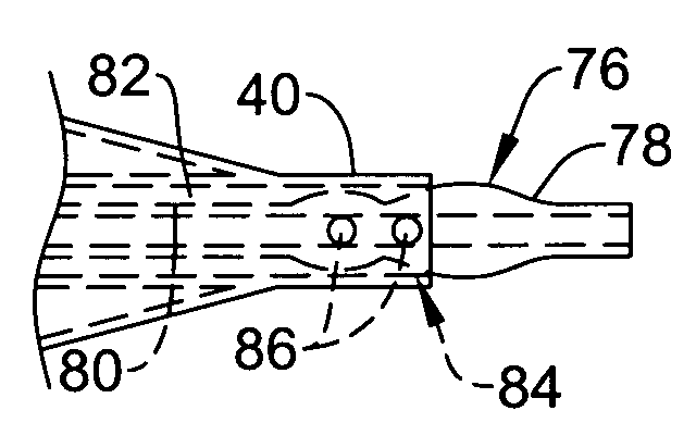
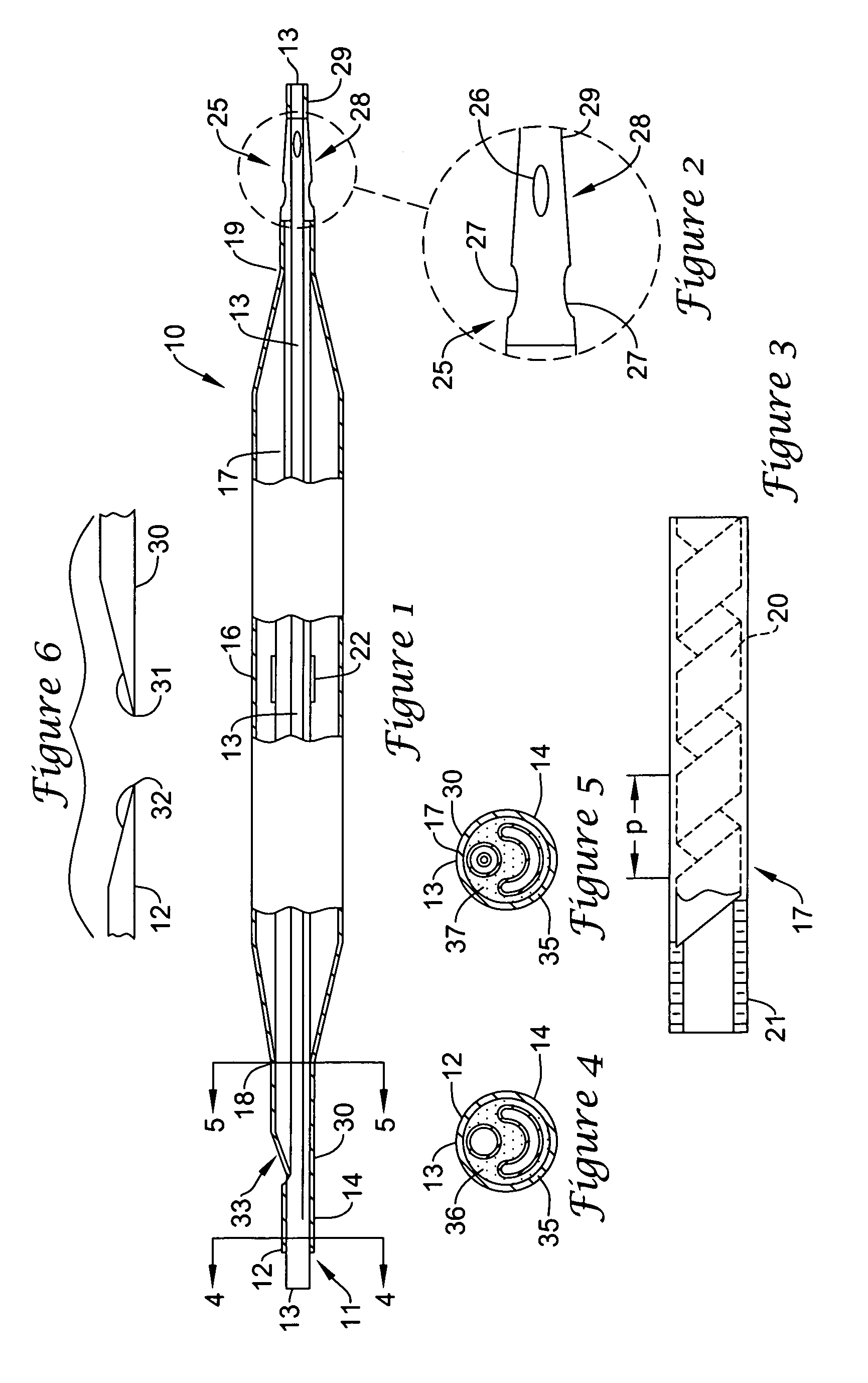
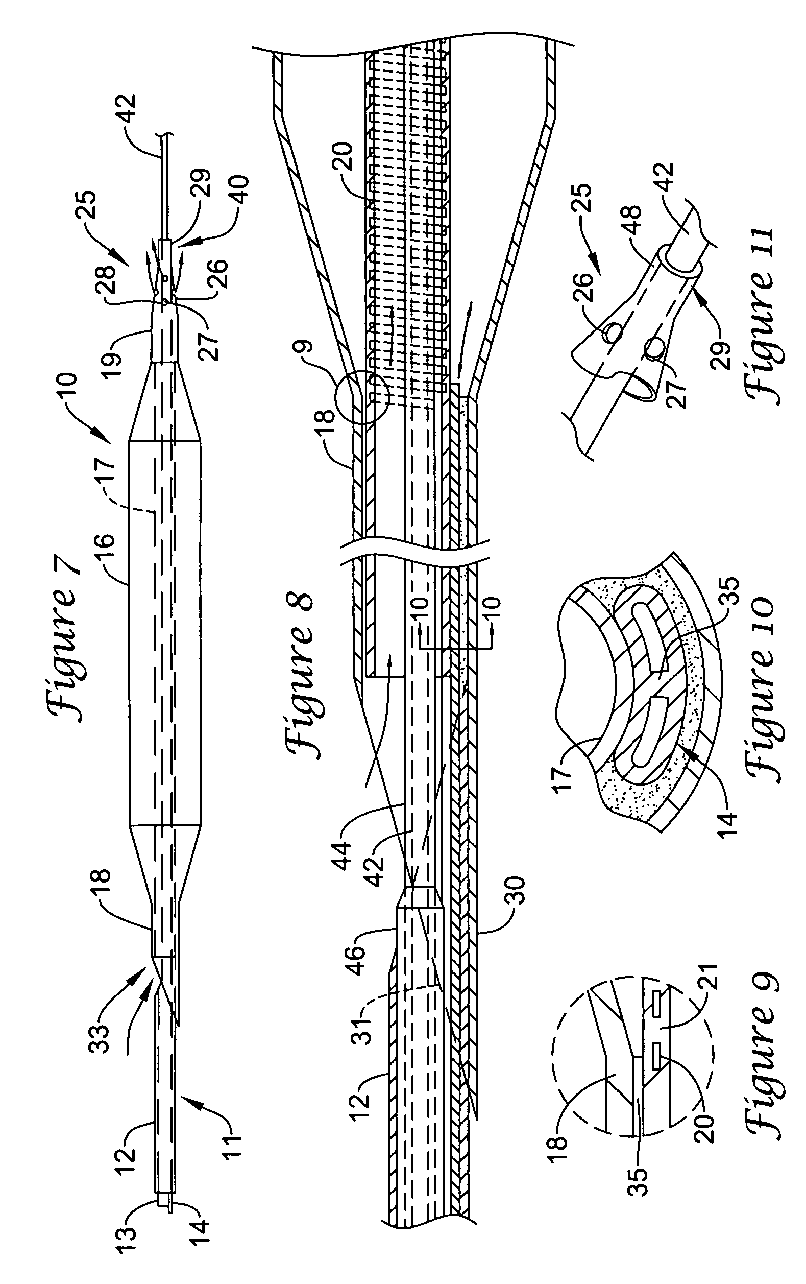
[0014]The present invention provides a perfusion balloon catheter particularly adapted to angioplasty of the type having a balloon assembly carried at the distal end of an elongated catheter body. The balloon assembly includes an inflatable balloon envelope and a perfusion lumen extending through the balloon envelope to provide a blood flow passage during inflation of the balloon envelope. In a preferred embodiment, the perfusion lumen is formed of an encapsulating flexible material supported against collapse during balloon inflation by a helical member having spaced coils. The pitch of the spaced coils may be selected to avoid coil-to-coil contact during traverse of a body vessel, as during advance of the catheter through the vascular system during delivery of the catheter to a desired site within the vessel. Blood flow through the perfusion lumen is facilitated in accordance with another aspect of the present invention through side opening configurations which facilitate discharge during perfusion. In a preferred embodiment, the discharge is through generally oval orifices. The orifices are located in a distally projecting tip, the tip being in fluid communication with the perfusion lumen. In a preferred embodiment, the major dimension of the oval orifices is generally aligned with the direction of projection of the projecting tip.
[0019]One embodiment of the invention allows for a smaller balloon catheter cross section by having the perfusion lumen proximal end be of large cross section, decreasing to a smaller cross section at the distal end. The smaller cross section at the distal end allows inserting the distal end of the balloon catheter into narrowed vessel regions, without unduly restricting blood flow through the perfusion lumen.
[0020]Another embodiment of the present invention allows for increasing blood flow through the perfusion lumen by having the guidewire lumen external to the perfusion lumen. By having the guidewire lumen outside of the perfusion lumen, the cross sectional area available for blood flow inside the perfusion lumen is increased.
[0021]Yet another embodiment of the present invention provides for a collapsible guidewire lumen. After inserting the balloon catheter over a guidewire, the guidewire may be backed out, thereby allowing the guidewire lumen to collapse. This collapse increases the cross sectional area available for blood flow in the perfusion lumen.

Problems solved by technology

As a result, this approach is inherently limited.
While this approach potentially offers nearly complete myocardial perfusion, it is complicated and cumbersome.
As the name implies, this requires some form of mechanical pump which complicates the angioplasty equipment and procedure.
Further, pressure within the balloon envelope during balloon inflation has a tendency to compress a perfusion lumen within the envelope thereby potentially constricting the blood flow passage.
On the other hand, countering this tendency by stiffening the perfusion lumen walls can seriously impact trackability of the catheter itself.

Method used


Image

  • Perfusion balloon angioplasty catheter
  • Perfusion balloon angioplasty catheter
  • Perfusion balloon angioplasty catheter

Examples


Embodiment Construction

[0062]FIG. 1 is a partial cut-away of a preferred embodiment of the present invention including a balloon head assembly generally designated at 10, the balloon head 10 being carried at the distal end 11 of an elongated catheter body (partially shown). The embodiment illustrated in FIG. 1 is an over-the-wire angioplasty balloon catheter. The distal terminus 11 of the catheter body includes an outer tubular member 12 surrounding an inner tubular guidewire lumen 13. The space between the outer surface of the guidewire lumen 13 and the inner surface of tubular member 12 provides a passage (an inflation lumen) for inflation of the balloon of balloon assembly 10, in known manner. In the illustrated embodiment, the tubular members 12 and 13 may be formed of polyethylene, for example, while those portions of the catheter body which are not illustrated may be of any conventional design, including a manifold. Fluid communication between the inflation lumen formed by the members 12 and 13 and ...


PUM


Abstract

A balloon angioplasty catheter having a balloon head assembly carried at the distal end of an elongated catheter body. The balloon head assembly includes an inflatable balloon envelope and a perfusion lumen extending through the balloon envelope to provide a blood flow passage during inflation of the balloon envelope. The invention also encompasses embodiments having a collapsible guidewire lumen for increasing perfusion blood flow upon guidewire withdrawal. Also within the scope of the invention is a distally stepped down perfusion catheter, allowing for decreased distal cross section. In another preferred embodiment, the perfusion lumen is inflatable. In yet another embodiment, the guidewire lumen is external to the perfusion lumen.

Description

CROSS REFERENCE TO RELATED APPLICATIONS[0001]This application is a continuation of application Ser. No. 08 / 612,061, filed Mar. 7, 1996, now abandoned which is a continuation-in-part of application Ser. No. 08 / 441,618, filed May 15, 1995, now U.S. Pat. No. 5,591,129 which in turn is a continuation-in-part of application Ser. No. 08 / 204,733, filed Mar. 2, 1994, now abandoned.BACKGROUND OF THE INVENTION[0002]The present invention relates to angioplasty and, in particular, to perfusion balloon angioplasty catheters.[0003]Balloon catheters are widely used in a variety of intravascular applications. In particular, angioplasty has gained wide acceptance as an efficient and effective treatment for particular vascular conditions. For example, angioplasty is widely used to treat stenoses in coronary arteries, although its application to stenoses in other parts of the vascular system is also known.[0004]The most common form of angioplasty is percutaneous transluminal coronary angioplasty (PTCA...

Claims


Application Information

Patent Timeline
IPC IPC(8): A61M29/00
CPCA61M25/104A61M2025/1095
Inventor COX, JAMES E.CORNELIUS, RICHARD G.EIDENSCHINK, TRACEE E. J.BOLDENOW, GREGORY A.REN, BROOKE Q.
Owner BOSTON SCI SCIMED INC
Learn More