Electrochromic mirror having variable reflectivity

a technology of reflectivity and mirror, applied in the field of rearview mirror, can solve the problems of high production cost, inability to form multi-layer films using vacuum deposition, and thin films that become colored once may not return to their original state, etc., and achieves the effects of low cost, simple structure and convenient manufacturing

Active Publication Date: 2006-08-08
KK TOKAI RIKA DENKI SEISAKUSHO
View PDF18 Cites 16 Cited by
  • Summary
  • Abstract
  • Description
  • Claims
  • Application Information

AI Technical Summary

Benefits of technology

[0018]On the other hand, as described above, the electrolytic solution contains the neutral molecules or the negative ions which can be oxidized, and thereby the above reduction reaction of the electrochromic film is guaranteed.
[0056]As described above, the electrochromic mirror of the invention can be easily manufactured at a low cost. In addition, no double images occur, and the electrochromic mirror has a simple structure and high performance.

Problems solved by technology

However, if the balance of the film thickness and film quality of each thin film described above is not kept in the electrochromic mirror 100, the thin film which becomes colored once may not return to its original state.
In addition, problems exist in that stringent production conditions are required and the formation of a multi-layer film using vacuum deposition is expensive since any variation in the film thickness largely influences the performance.
Therefore, so-called double images occur, and it is extremely difficult to see by using the mirror.
In particular, since a mirror for a car is generally curved, a problem exists in that it is extremely difficult to manufacture the mirror, and thus the cost is high.

Method used


Image

  • Electrochromic mirror having variable reflectivity
  • Electrochromic mirror having variable reflectivity
  • Electrochromic mirror having variable reflectivity

Examples


first embodiment

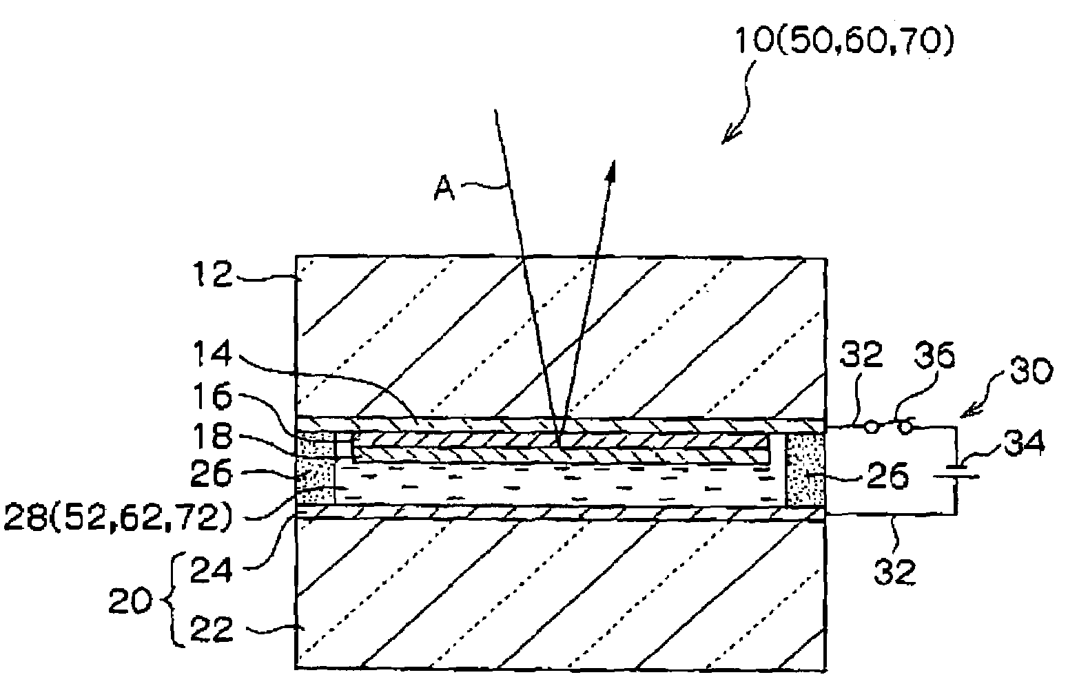
[0060]FIG. 1 is a cross-sectional view of the construction of the electrochromic mirror 10 of a first embodiment of the invention.

[0061]The electrochromic mirror 10 has a glass substrate 12 which is a transparent substrate. A transparent electrode film 14 is formed in the form of a thin film on the back surface of the glass substrate 12 by vacuum deposition or the like (the surface at the lower side in FIG. 1). The transparent electrode film 14 is a so-called “ITO film” made of a mixture of indium oxide and tin oxide in the first embodiment.

[0062]An electrochromic film 16 which can be colored by reduction is formed in the form of a thin film on the transparent electrode film 14 by vacuum deposition or the like. The electrochromic film 16 is made of tungsten trioxide (WO3) in the first embodiment.

[0063]A light reflecting film 18 is formed in the form of a thin film on the electrochromic film 16 by vacuum deposition or the like. The light reflecting film 18 is made of rhodium in the f...

second embodiment

[0084]Next, the second embodiment of the invention will be described. The same structure and action as those of the first embodiment are designated by the same reference numerals as in the first embodiment, and descriptions thereof are omitted.

[0085]As shown in FIG. 1, an electrochromic mirror 50 of the second embodiment has the same structure as that of the electrochromic mirror 10 of the first embodiment, except that an electrolytic solution is different from that of the first embodiment. A solvent of the electrolytic solution 52 of the electrochromic mirror 50 is propylene carbonate, and the electrolytic solution 52 contains lithium perchlorate (LiClO4) as a lithium ion agent and ferrocene (Fe(C5H5)2) which is a neutral material as a redox agent.

[0086]When the switch 36 of the power supply 30 is turned on in the electrochromic mirror 50, a negative voltage is applied to the transparent electrode film 14 and a positive voltage is applied to the electrode film 24 by the direct-curr...

third embodiment

[0095]Next, the third embodiment of the invention will be described. The same structure and action as those of the first embodiment are designated by the same reference numerals as in the first embodiment, and descriptions thereof are omitted.

[0096]As shown in FIG. 1, an electrochromic mirror 60 of the third embodiment has the same structure as that of the electrochromic mirror 10 of the first embodiment, except that an electrolytic solution is different from that of the first embodiment. A solvent of the electrolytic solution 62 of the electrochromic mirror 60 is propylene carbonate, and the electrolytic solution 62 contains ferrocyanic acid (H4[Fe(CN)6])as an electrolyte.

[0097]When the switch 36 of the power supply 30 is turned on in the electrochromic mirror 60, a negative voltage is applied to the transparent electrode film 14 and a positive voltage is applied to the electrode film 24 by the direct-current power supply 34. As a result, reduction reaction which is the same as the...


PUM

PropertyMeasurementUnit
electrochromicaaaaaaaaaa
transparentaaaaaaaaaa
conductivityaaaaaaaaaa

Abstract

The present invention provides an electrochromic mirror including: a transparent substrate; a transparent electrode film which is formed on the transparent substrate and has conductivity; an electrochromic film which is formed on the transparent electrode film and can be colored by reduction; a light reflecting film which is formed on the electrochromic film and which hydrogen atoms or lithium atoms can permeate; a support substrate which has a conductive part having conductivity formed on at least one surface thereof; and an electrolytic solution containing at least hydrogen ions or lithium ions, and neutral molecules or negative ions which can be oxidized, wherein the transparent substrate is located close to the support substrate such that the conductive part faces the light reflecting film, and the electrolytic solution is enclosed between the light reflecting film and the conductive part.

Description

CROSS-REFERENCE TO RELATED APPLICATION[0001]This application claims priority under 35 USC 119 from Japanese Patent Application Nos. 2003-173101 and 2004-56387, the disclosures of which are incorporated by reference herein.BACKGROUND OF THE INVENTION[0002]1. Field of the Invention[0003]The present invention relates to a rearview mirror for indoor or outdoor use which is applied to a vehicle such as a car, and more particularly, to an electrochromic mirror in which the reflectivity can be changed by applying voltage.[0004]2. Description of the Related Art[0005]Conventionally, an “electrochromic mirror” is known (for instance, see Japanese Utility Model Application Publication (JP-Y) No. 62-2587). An electrochromic mirror may be used as a rearview mirror for a vehicle such as a car and can electrically change the reflectivity so as to reduce the glare of the headlight of a following car at night.[0006]As shown in FIG. 2, in an electrochromic mirror 100 disclosed in JP-Y No. 62-2587, a ...

Claims


Application Information

Patent Timeline
Patent Type & Authority Patents(United States)
IPC IPC(8): G02F1/15B60R1/08G02F1/157
CPCB60R1/088G02F1/157
Inventor NAKAHO, JUNICHIAYABE, MASAOHATTORI, MASAHARU
Owner KK TOKAI RIKA DENKI SEISAKUSHO
Why Eureka
Try Eureka