Outer ring member for constant velocity joint and method of manufacturing the member

a constant velocity joint and outer ring technology, which is applied in the direction of furnaces, heat treatment furnaces, heat treatment apparatus, etc., can solve the problems of difficult to inexpensively supply and the inability to efficiently manufacture the outer ring member b>1/b> for the barfield-type constant velocity joint, so as to improve the quality and product accuracy of the finished product, improve the accuracy of the groove formation, and improve the effect of quality and product accuracy

Inactive Publication Date: 2006-08-15
HONDA MOTOR CO LTD
View PDF9 Cites 6 Cited by
  • Summary
  • Abstract
  • Description
  • Claims
  • Application Information

AI Technical Summary

Benefits of technology

[0022]As described above, in the present invention, the ironing step is subsequently performed before the formed product obtained by the backward extrusion causes the work hardening. Therefore, it is possible to disuse the low temperature annealing treatment, the shot blast treatment, and the formation of the lubricating chemical conversion coating. That is, it is preferable that the backward extrusion step and the ironing step are performed continuously.
[0023]Further, in the present invention, it is possible to improve the stability of quality and the product accuracy of the finished product to be manufactured in the downstream steps by forming the intermediate preformed product by using a preforming die before performing the backward extrusion. In particular, it is possible to improve the accuracy of grooves formed on the inner wall surface of the cup section of the outer ring member for the constant velocity joint as the finished product.
[0024]As clearly understood from the above, the outer ring member for the constant velocity joint can be efficiently manufactured by continuously applying the ironing to the formed product immediately after the backward extrusion to the intermediate preformed product. That is, the outer ring member for the constant velocity joint can be mass-produced in a short period of time. Therefore, it is possible to supply the outer ring member for the constant velocity joint inexpensively.
[0025]It is preferable that the ironing is performed after applying a liquid lubricant to either one of or both of a surface of the formed product immediately after performing the backward extrusion step for the intermediate preformed product and a die to be used to perform the ironing, for the following reason. The procedure as described above makes it possible to avoid occurrence of galling on the formed product or the die for the ironing during the execution of the ironing for the formed product.

Problems solved by technology

In other words, in the conventional production method, it is impossible to efficiently manufacture the outer ring member 1 for the barfield-type constant velocity joint.
Further, it is inevitably difficult to inexpensively supply the outer ring member 1 for the barfield-type constant velocity joint under the situation since it is impossible to mass-produce the outer ring member 1 for the barfield-type constant velocity joint as described above.

Method used


Image

  • Outer ring member for constant velocity joint and method of manufacturing the member
  • Outer ring member for constant velocity joint and method of manufacturing the member
  • Outer ring member for constant velocity joint and method of manufacturing the member

Examples


Embodiment Construction

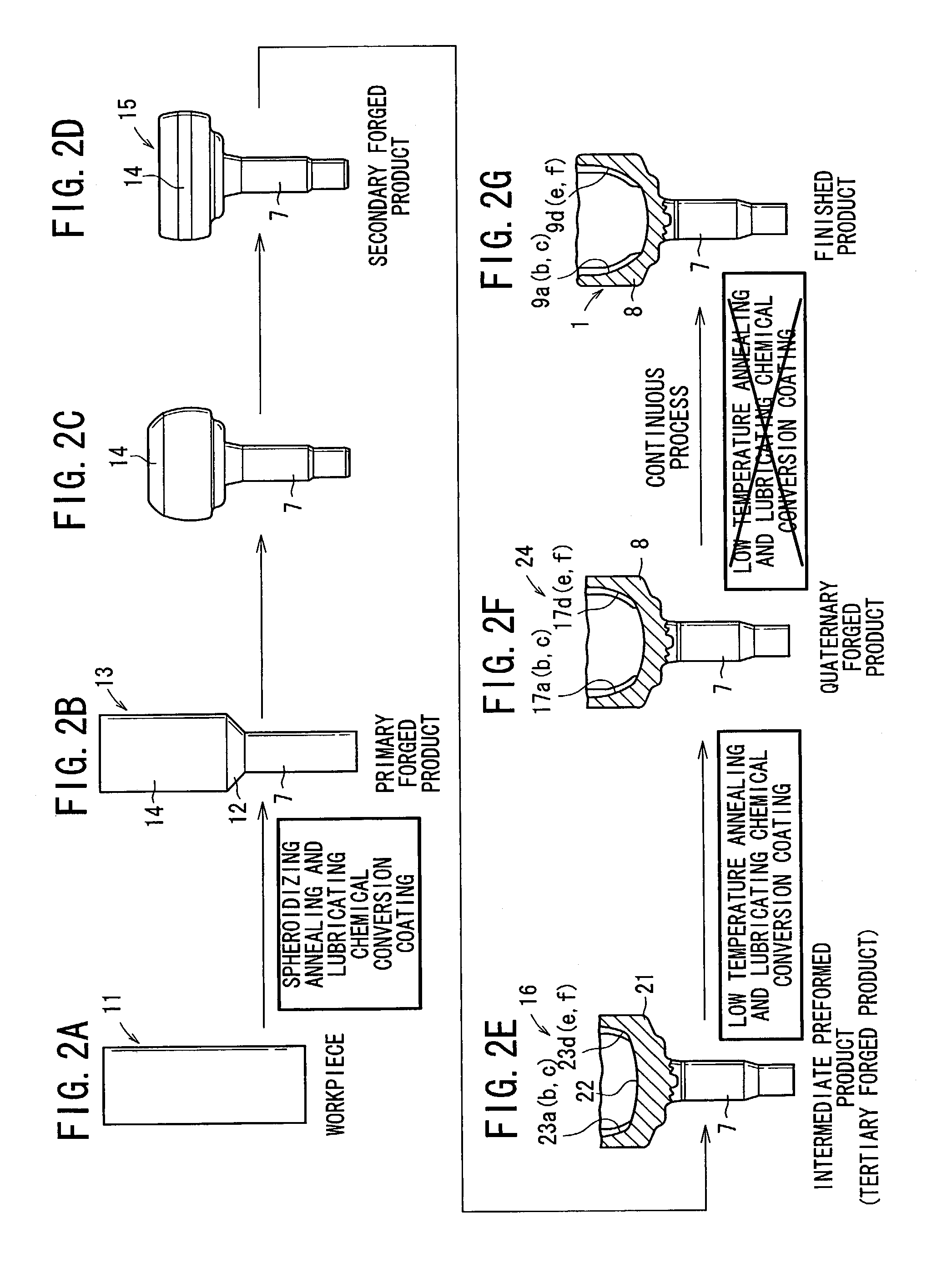
[0040]The outer ring member for the constant velocity joint according to the present invention will be explained in detail with reference to the accompanying drawings, as exemplified by preferred embodiments in relation to the method of manufacturing the member. The constitutive components that are same as the constitutive components shown in FIG. 10 to FIGS. 13A to 13F are designated by the same reference numerals, and detailed explanation thereof will be omitted.

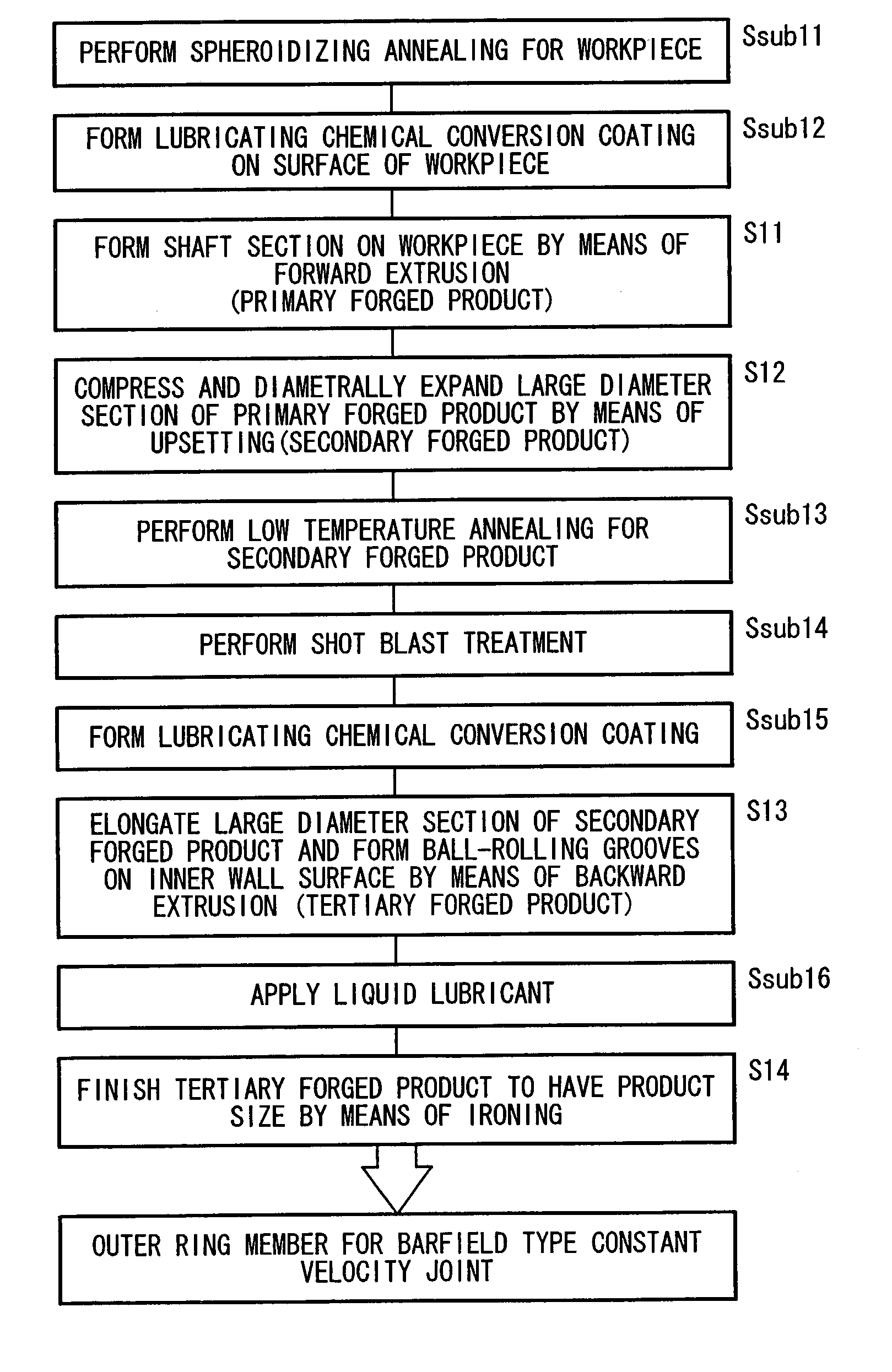
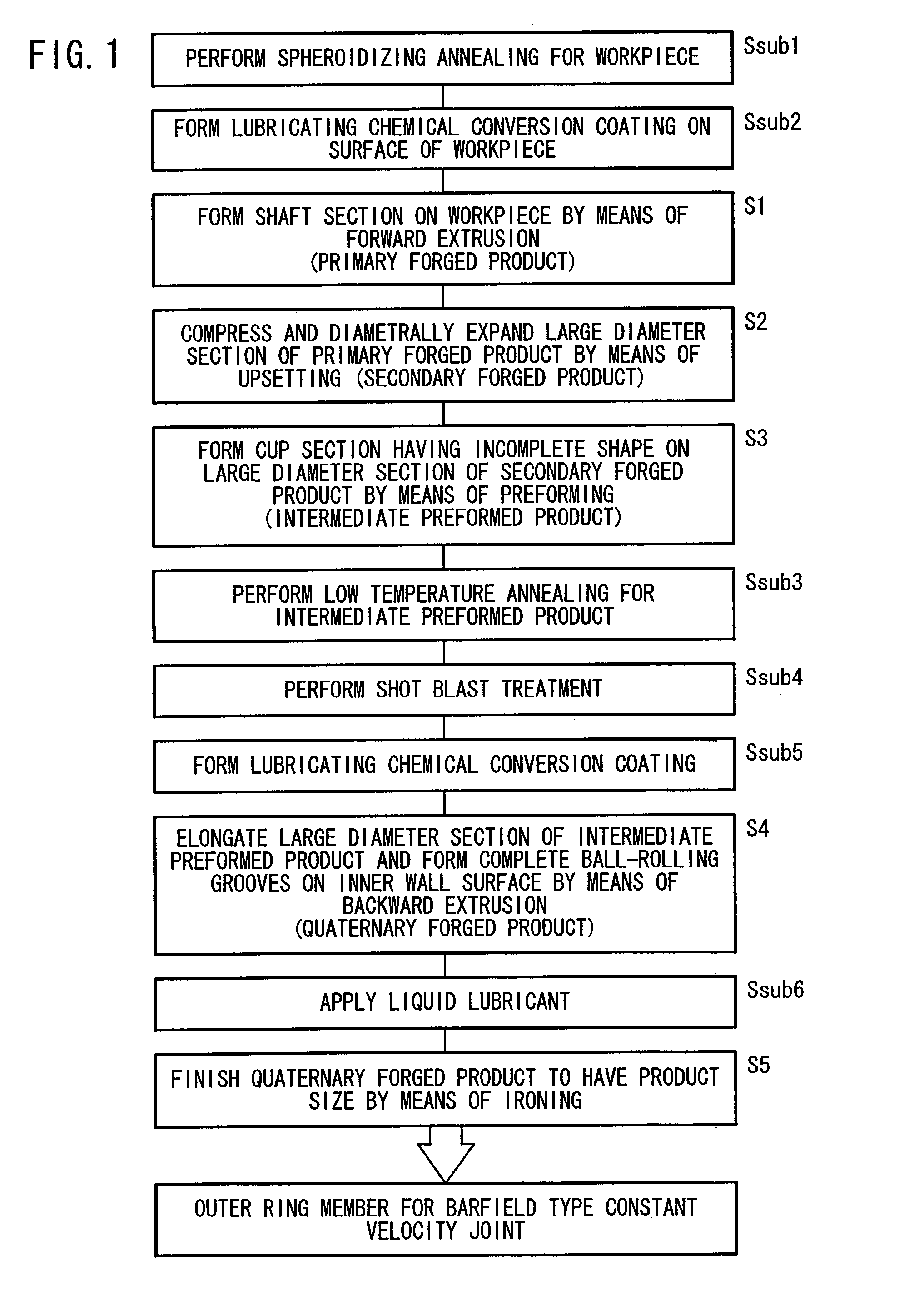
[0041]In a method of manufacturing an outer ring member for a constant velocity joint according to an embodiment of the present invention, as shown in a flow chart in FIG. 1, the cold forging processes are applied five times to a workpiece 11 of a columnar material made of carbon steel, and the outer ring member 1 for the barfield-type constant velocity joint (see FIGS. 11 and 12) is finally manufactured.

[0042]Respective steps of the production method according to the embodiment of the present invention are shown in FIGS. ...


PUM

PropertyMeasurementUnit
temperatureaaaaaaaaaa
constant velocityaaaaaaaaaa

Abstract

An outer ring member for a constant velocity joint is manufactured. An intermediate preformed product having a cup section with an incomplete shape is formed by pressing a large diameter section without applying a low temperature annealing treatment and a lubricating chemical conversion coating treatment. Then, applying a low temperature annealing treatment and a lubricating chemical conversion coating treatment to the intermediate preformed product, thereafter a formed product having a cup section provided with ball-rolling grooves is formed by backward extrusion to the intermediate preformed product. Subsequently, the product is ironed before hardening, without applying a low temperature annealing treatment and a lubricating chemical conversion coating treatment to the formed product.

Description

[0001]This application is the national phase under 35 U.S.C. §371 of PCT International Application No. PCT / JP02 / 06482 which has an International filing date of Jun. 27, 2002, which designated the United States of America.TECHNICAL FIELD[0002]The present invention relates to an outer ring member for a constant velocity joint and a method of manufacturing the member. In particular, the present invention relates to an outer ring member for a constant velocity joint which can be manufactured efficiently, and a method of manufacturing the member.BACKGROUND ART[0003]FIG. 10 shows a driving force transmission mechanism which is carried on an automobile or the like and which is used to transmit the driving force from an internal combustion engine to axles. In the driving force transmission mechanism, outer ring members 1, 1 for a barfield-type constant velocity joint and outer ring members 2, 2 for a tripod-type constant velocity joint are connected to one another by spline shafts 3, 3. A d...

Claims


Application Information

Patent Timeline
Patent Type & Authority Patents(United States)
IPC IPC(8): C21D7/02C21D9/40B21K1/76F16D3/223
CPCB21K1/762F16D3/223F16D2250/00
Inventor OOHAMA, TSUKASHISATO, NAOMIDOI, YOSHIHISAAKIMOTO, SABUROOTA, SHIGEO
Owner HONDA MOTOR CO LTD
Why Eureka
Try Eureka