
Control system architecture for a multi-component armament system

a control system and multi-component technology, applied in the field of multi-component armament or weaponry systems, can solve the problems that the delivery of messages is usually not deterministic, and achieve the effects of improving system robustness, promoting system scalability, and overcompensating slow points and broken lines of communication

Inactive Publication Date: 2006-08-15
BAE SYSTEMS LAND & ARMAMENTS LP
View PDF26 Cites 34 Cited by
  • Summary
  • Abstract
  • Description
  • Claims
  • Application Information

AI Technical Summary

Benefits of technology

[0042]The present invention is a Control System Architecture (CSA) for a multi-component armament system. The CSA provides dynamic reconfiguration of multiple nodes (e.g., a component, a subsystem, or a virtual simulation) in a Simulation-Emulation-Stimulation (SES) environment utilizing redundant client-server bus configuration of the nodes in a hierarchical model. The CSA provides for ease of configuration of nodes for any specific application, automated system reconfiguration capabilities to detect and bypass failed nodes or re-group available remaining nodes in the event of degraded mode operation, and expansion and / or downsizing of nodes without requiring a modification to the overall system architecture.
[0043]Unlike existing control systems that connect all of the armament components to a common bus controlled by a single controller, various components of the CSA are preferably connected in a web-like topology. The use of a single common bus to interconnect multiple components of an armament system has been dictated by the need for well defined communications between the controller and the armament components. A signal to fire a weapon must be delivered to that component in a timely manner. The single bus single controller architecture enables existing systems to be designed such that control signals will arrive when expected. In contrast, a web-like topology provides for multiple communication paths between components and, as such, delivery of messages usually is not accomplished in a deterministic manner. To overcome this, the present invention utilizes a real-time scheduler within the CSA to monitor communications in the client-server architecture. The scheduler enables the CSA to overcome slow points and broken lines of communication while still preserving the predictable time response required of an armament system. This imparts an increased robustness to the system that is not found in the prior art armament systems, each of which featuring point-to-point communications topology.
[0044]One embodiment of the present invention provides for a client-server type multi-tiered hierarchical network for controlling a multi-component armament system. In one case, the top level of the system comprises a system controller. The system controller is comprised of an input / output management (IM) server, a notational controller (NC) server, and several placeholder (PH) servers. The second layer is comprised of a man-machine-interface (MMI) client, a plant model client, and a controller client. The third layer is comprised of first and second graphical user interfaces (GUI's) and a test stand. The MMI is configurable to operate either a virtual prototype of an armament component, a real version of the armament component, or both. The switching between the virtual prototype, real prototype, or both is preferably accomplished by the inclusion of an A / B / C switch programmably included in the system controller software. The inclusion of the A / B / C switch in the hierarchical client-server architecture allows the CSA to be reconfigured during system development and test. Additionally, the hierarchical nature of the CSA promotes system scalability, in that new nodes can be added to or subtracted from a level, and even new levels can be added to the system. The scalability feature allows the system architecture to be easily modified, upgraded and maintained.

Problems solved by technology

In contrast, a web-like topology provides for multiple communication paths between components and, as such, delivery of messages usually is not accomplished in a deterministic manner.

Method used


Image

  • Control system architecture for a multi-component armament system
  • Control system architecture for a multi-component armament system
  • Control system architecture for a multi-component armament system

Examples


Embodiment Construction

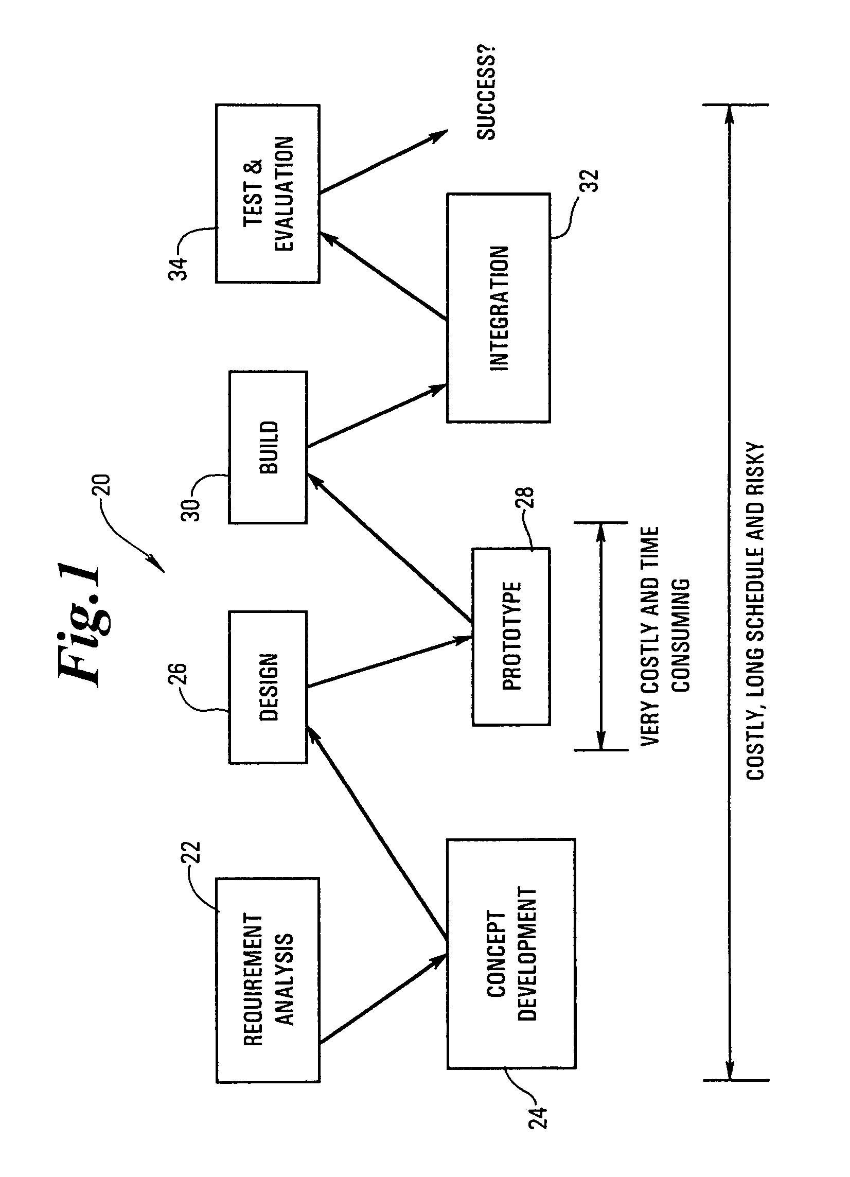
[0067]Referring to FIG. 1, the prior art conventional engineering development process is shown generally at 20. The steps of the prior art design process are, in order, generation of system requirements 22, development of concepts 24, produce designs based on the concepts 26, prototyping 28, building individual systems 30, integrating those individual systems 32, and performing testing and evaluation of the completed system 34. If the testing and evaluation stage 34 revealed that the particular design is not acceptable, then the process must be reiterated starting back at the prototype stage 28, or earlier.

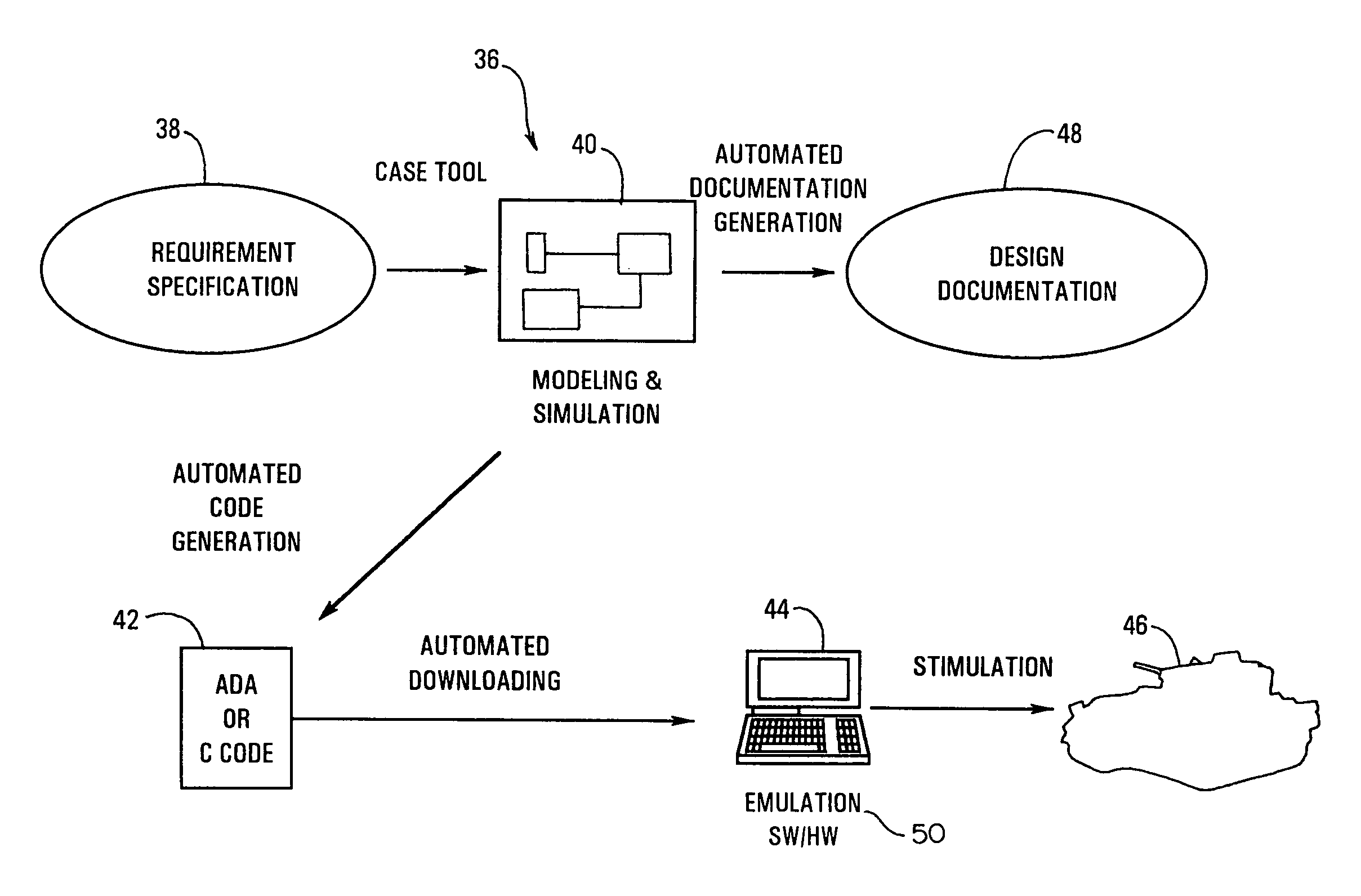
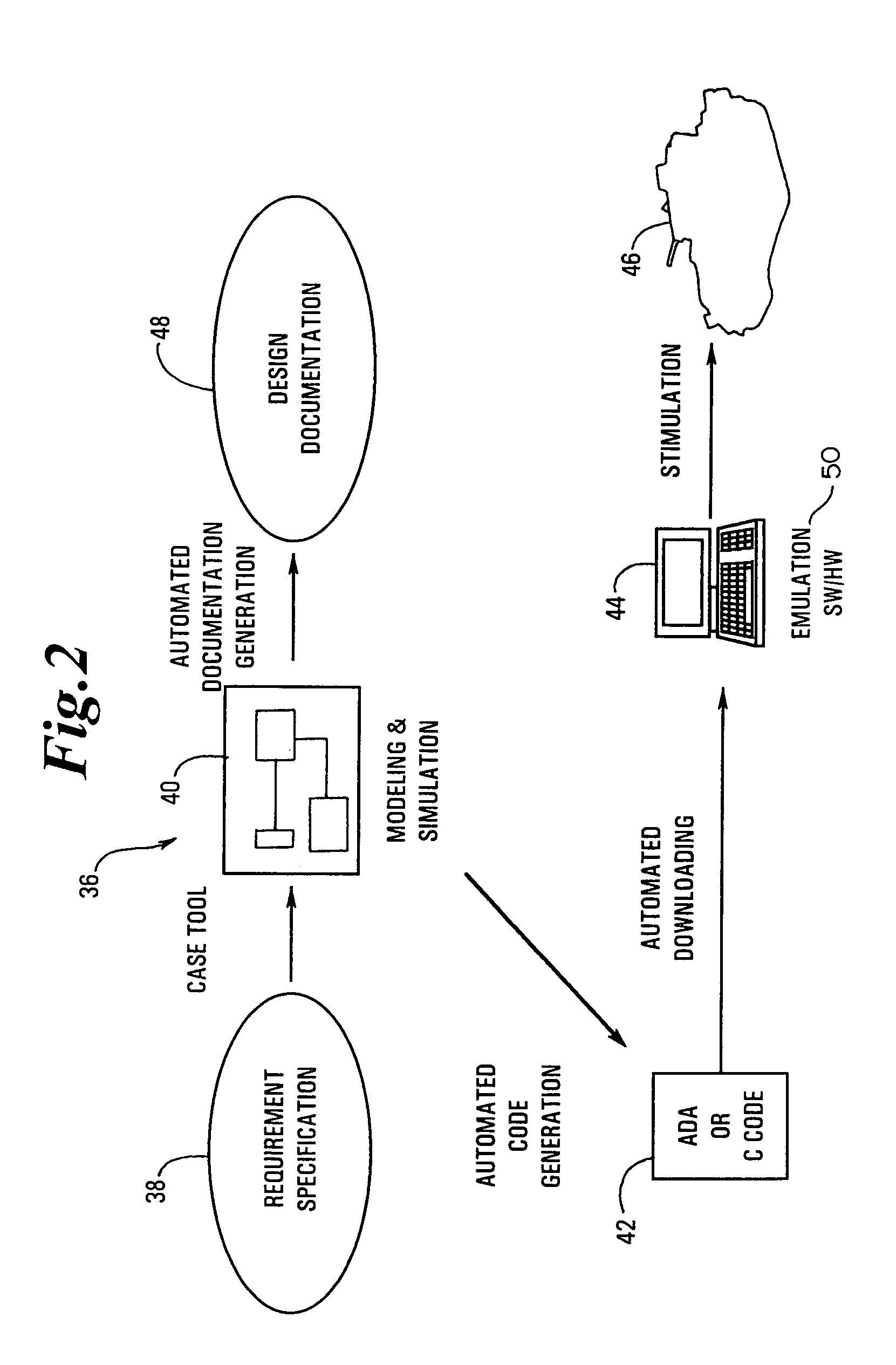
[0068]Referring to FIG. 2, the Simulation-Emulation-Stimulation (SES) process, generally designated at 36 minimizes the required iterations and condenses the steps of the prior conventional development process. SES comprises the steps of using system specifications to generate a set of system requirements 38, performing modeling and simulation (M&S) 40 of the multi-component armam...


PUM


Abstract

The present invention is a Control System Architecture (CSA) for a multi-component armament system. The CSA provides dynamic reconfiguration of multiple nodes (e.g. a component, a subsystem, or a virtual simulation) in a Simulation-Emulation-Stimulation (SES) environment utilizing redundant client-server bus configuration of the nodes in a hierarchical model. The CSA provides for ease of configuration of nodes for any specific application, automated system reconfiguration capabilities to detect and bypass failed nodes or re-group available remaining nodes in the event of degraded mode operation, and expansion and / or downsizing of nodes without requiring a modification to the overall system architecture.

Description

FIELD OF THE INVENTION[0001]The present invention relates to multi-component armament or weaponry systems. More particularly, the present invention relates to a robust control system architecture for simulation and control of multi-component armament systems.BACKGROUND OF THE INVENTION[0002]Modem armament systems for military applications are increasingly complex. Typically, there are a plurality of disparate components that are controlled by a complex control system, which coordinates and integrates the operation of each component in the system.[0003]In the early stages of evolution, armament control systems were merely a series of mechanical mechanisms that allowed an operator to activate a particular component using the judgment of the operator. One such example is the mechanical linkage for weapons release on early military aircraft. When the pilot determined the plane was at the correct location, the pilot would actuate a particular linkage from the cockpit, thereby releasing t...

Claims


Application Information

Patent Timeline
IPC IPC(8): G06F13/10F41H13/00G06F15/00H04L12/24H04L12/26
CPCH04L41/22H04L41/0631H04L41/0654G06F15/16
Inventor HUANG, PAUL C.KHAN, OMAR A.SLEDER, JR., ALBERT
Owner BAE SYSTEMS LAND & ARMAMENTS LP
Learn More