Dialyzer and method for manufacturing the same

a dialyzer and manufacturing method technology, applied in the field of dialyzer, can solve the problems of irregular inner diameter of the hollow fiber membrane during manufacture, affecting the flow path of dialyzer, and the possibility of hollow fiber membrane rupture, etc., to achieve the effect of simple structure and decreasing the sectional area of the dialyzer flow path

Inactive Publication Date: 2006-08-22
NIPRO CORP
View PDF12 Cites 10 Cited by
  • Summary
  • Abstract
  • Description
  • Claims
  • Application Information

AI Technical Summary

Benefits of technology

[0019]Under these circumstances, an object of the invention is to provide a dialyzer which can solve the foregoing problems associated with conventional dialyzers. More specifically, an object of the invention is to provide a dialyzer which is simple in structure without fear of rupturing hollow fiber membranes during fabrication and in which an internal filtration rate and an internal backfiltration rate are increased by decreasing a sectional area of the dialyzate flow path.

Problems solved by technology

Such a dialyzer is impractical.
Further, in the dialyzer with the inner diameter of the hollow fiber membrane decreased, there is a likelihood that irregularity occurs in the inner diameter of the hollow fiber membrane during manufacture or blood remaining in lumens of the hollow fiber membranes after use of the dialyzer is increased.
Therefore, the hollow fiber membranes might be ruptured and the packing ratio of the hollow fiber membranes inserted into the case is not high enough.
When the amount of the bonded mat is large, it is difficult to insert the hollow fiber bundle into the case of the dialyzer.
Meanwhile, when the amount of the bonded mat is small, the sectional area of the dialyzate flow path is not sufficiently lowered.
On the other hand, in a dialyzer in which a bag-shaped member is swelled, the structure is complicated and a force exerted in swelling the bag-shaped member is also exerted on the case of the dialyzer.
With such a dialyzer, pressure has to be continued to be applied during changing of the sectional area of the dialyzate flow path so that the structure of the dialyzer is more complicated.

Method used


Image

  • Dialyzer and method for manufacturing the same
  • Dialyzer and method for manufacturing the same
  • Dialyzer and method for manufacturing the same

Examples


example 1

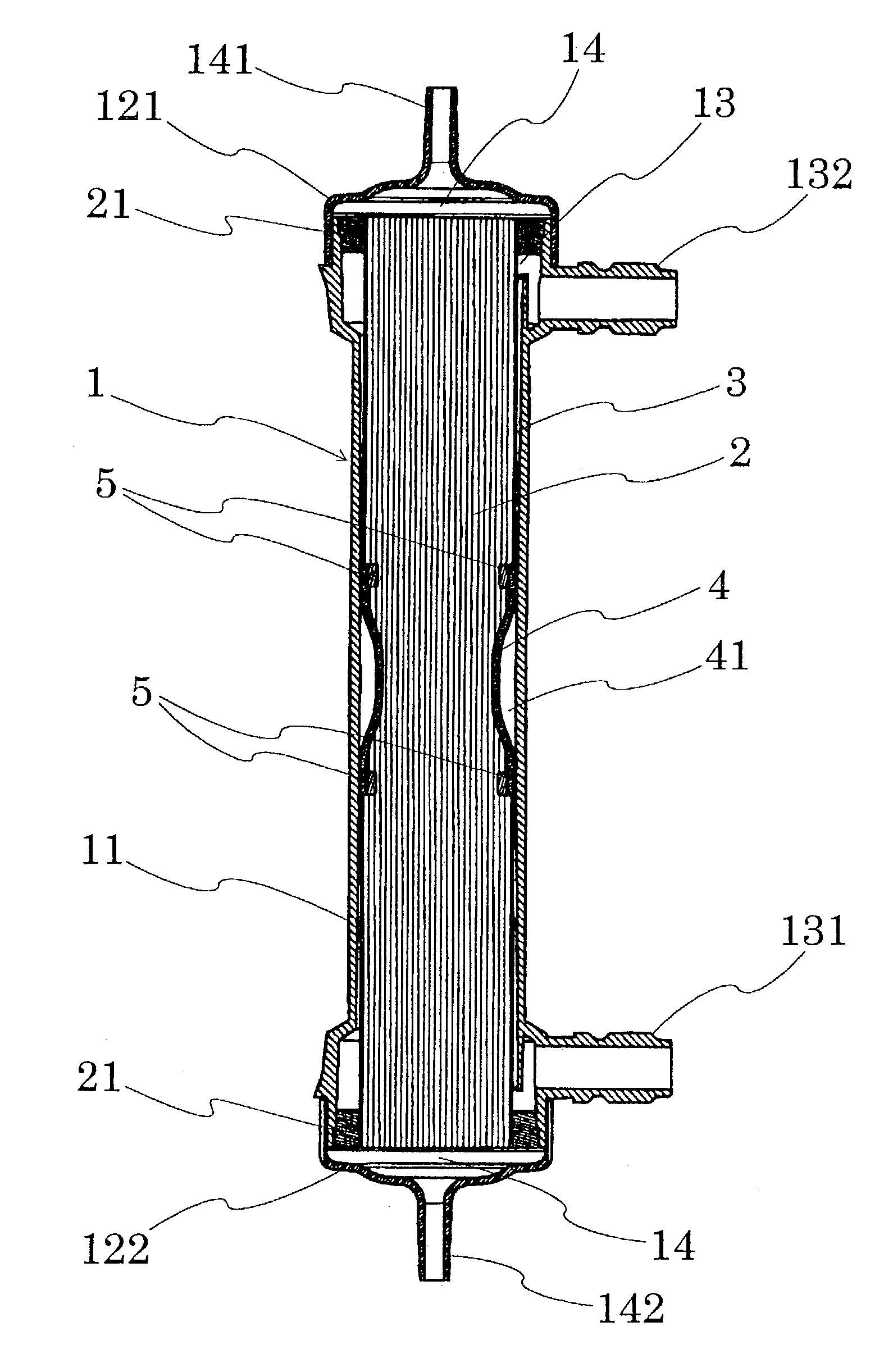
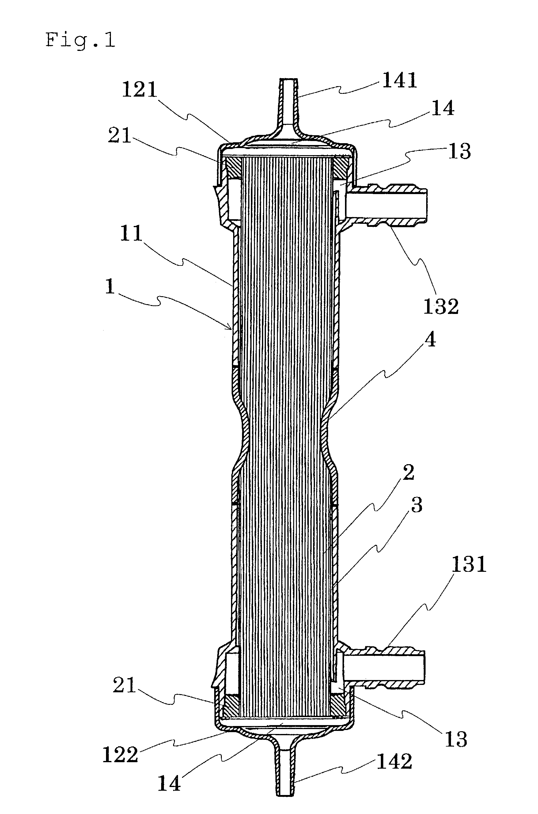
[0067]A tube made of polytetrafluoroethylene (hereinafter abbreviated as PTFE) and having a total length of 60 mm and an outer diameter of 36 mm was inserted into a central portion of a case body of a dialyzer made of polycarbonate and having a total length of 272 mm and an inner diameter of 36.5 mm. Subsequently, a hollow fiber bundle obtained by bundling approximately 9,000 hollow fiber membranes each made of polyether sulfone and having an inner diameter of 200 μm and an outer diameter of 260 μm was inserted into the lumen of the tube. A potting agent was injected into both ends of the case body to fix the hollow fiber bundle in the case body. An effective membrane area of the hollow fiber bundle was 1.5 m2, and a packing ratio of the hollow fiber bundle was 45%. Then, the case body in the dialyzer was heated at 100° C. with a heater from an outer surface of the case body to locally heat and shrink the central portion of the PTFE tube, and caps were then mounted on both ends of t...

example 2

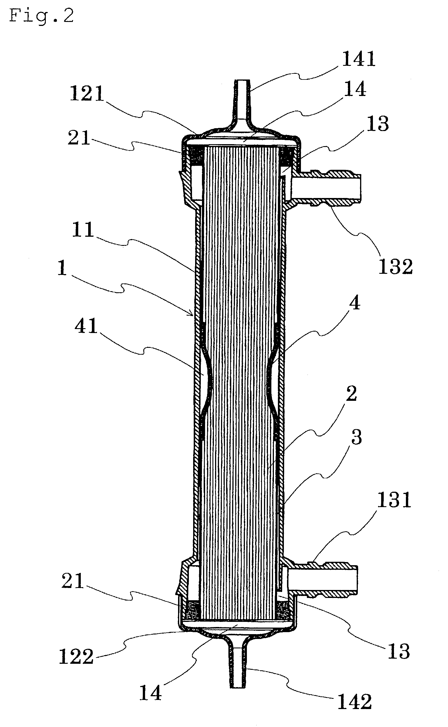
[0068]A PTFE tube having a total length of 60 mm and an outer diameter of 36 mm was inserted into a central portion of a case is body of a dialyzer made of polycarbonate and having a total length of 272 mm and an inner diameter of 36.5 mm. Further, rings each having a cross-section which is a trapezium made of polycarbonate and having an inner diameter of 34.0 mm, an outer diameter of 35.5 mm at a distal end and an outer diameter of 36.5 mm at a proximal end were inserted into both ends of the lumen of the tube to fix the tube in the case body. Subsequently, a hollow fiber bundle obtained by bundling approximately 9,000 hollow fiber membranes each made of polyether sulfone and having an inner diameter of 200 μm and an outer diameter of 260 μm was inserted into the lumen of the tube. A potting agent was injected into both ends of the case body to fix the hollow fiber bundle in the case body. An effective membrane area of the hollow fiber bundle was 1.5 m2, and a packing ratio of the ...

example 3

[0069]A PTFE tube having a total length of 60 mm and an outer diameter of 36 mm was inserted into a central portion of a case body of a dialyzer made of polycarbonate and having a total length of 272 mm and an inner diameter of 36.5 mm. Subsequently, a hollow fiber bundle obtained by bundling approximately 9,000 hollow fiber membranes each made of polyether sulfone and having an inner diameter of 200 μm and an outer diameter of 260 μm was inserted into the lumen of the tube. A potting agent was injected into both ends of the case body to fix the hollow fiber bundle in the case body. An effective membrane area of the hollow fiber bundle was 1.5 m2, and a packing ratio of the hollow fiber bundle was 45%. Then, the case body in the dialyzer was heated at 100° C. with a heater from an outer surface of the case body to locally heat and shrink the central portion of the PTFE tube. Moreover, the case body was deformed to abut on the tube by being heated with a heater, and caps were then mo...


PUM

PropertyMeasurementUnit
areaaaaaaaaaaa
areaaaaaaaaaaa
thicknessaaaaaaaaaa

Abstract

A dialyzer in which a nearly cylindrical case is provided therein with a hollow fiber bundle made of a plurality of hollow fiber membranes, a blood flow path formed by lumens of the hollow fiber membranes, a dialyzate flow path formed by a space between the inner wall of the case and the hollow fiber membranes and a cylindrical heat-shrinkable tube provided on the outside of the hollow fiber bundle and at least a part of which can be shrunk by heating, and a method for manufacturing the dialyzer.

Description

BACKGROUND OF THE INVENTION[0001]The present invention relates to a dialyzer used in dialysis. More specifically, it relates to an internal filtration accelerating-type dialyzer which can increase an internal filtration rate and an internal backfiltration rate within the dialyzer.[0002]For therapy of patients whose renal function is impaired, for example, patients whose function of removing waste products or the like in blood is impaired because of renal insufficiency or the like, therapy by blood purification such as hemodialysis or hemodialytic filtration has so far been performed. In this blood purification therapy, urea, creatinine, uric acid, low-molecular proteins, water and the like accumulated in blood are removed by bringing the blood into contact with a dialyzate through semipermeable membranes in a dialyzer.[0003]In recent years, a substance that causes amyloidosis, which is one of complications in dialysis, has been identified as β2 microglobulin having a molecular weigh...

Claims


Application Information

Patent Timeline
Patent Type & Authority Patents(United States)
IPC IPC(8): B01D63/02C02F1/44A61M1/16A61M1/18B01D61/30B01D65/00
CPCA61M1/16B01D61/30B01D65/00B01D63/02B01D2313/23
Inventor SUNOHARA, TAKASHIYAMAGUCHI, AKINOBU
Owner NIPRO CORP
Why Eureka
Try Eureka