Dimensionally controlled pack aluminiding of internal surfaces of a hollow article

Inactive Publication Date: 2006-08-22
GENERAL ELECTRIC CO
View PDF9 Cites 2 Cited by
  • Summary
  • Abstract
  • Description
  • Claims
  • Application Information

AI Technical Summary

Benefits of technology

[0009]The present invention provides a method for aluminiding an internal surface of an internal cavity. The technique uses a pack aluminiding process to achieve a precisely controlled aluminide coating which is not so thick as to substantially impede airflow from the small-diameter outlets and not so thick as to promote low cycle fatigue cracking in the shank portion of the internal surface. The aluminiding source powder is selected so that the thickness of the coating is limited to the desired range of less than about 0.002 inch. The powder selection also ensures that the aluminiding source powder may be readily introduced into the internal cavity and also may be readily removed after the coating process is complete.
[0016]The present approach achieves aluminide coating of the internal surfaces to a precisely limited and controlled thickness of less than about 0.002 inches. Thicker coatings tend to reduce the minimum dimension of the outlet cooling holes by an unacceptably large amount, adversely affecting the in-service performance of the article. Thicker coatings also promote low cycle fatigue failure in the shank portion of the turbine blade. Conventional vapor phase aluminiding processes such as chemical vapor deposition processes deposited overly thick coatings in the interior of the shank portion of the turbine blade and in the bores of the outlet cooling holes, thereby reducing the effective flow diameter of the holes and thence the cooling performance of the air flow. The pack aluminiding technique, particularly when used with the preferred mix of aluminum-containing and ceramic powders, permitted the coating to be controllably applied in the desired thickness range. Additionally, chemical vapor deposition sometimes penetrates through masks to deposit on unintended regions of the article, which does not occur with the present internal pack aluminiding approach.
[0018]The present approach thus provides a powder-based aluminiding technique for internal cavities. The powder may be readily introduced and later removed from the internal cavity, and does not become entrapped in the outlet cooling holes. The use of the powder technique, with the correct powder size range and the correct proportions of powder, achieves controllable internal aluminide coating of the proper thickness in all regions.

Problems solved by technology
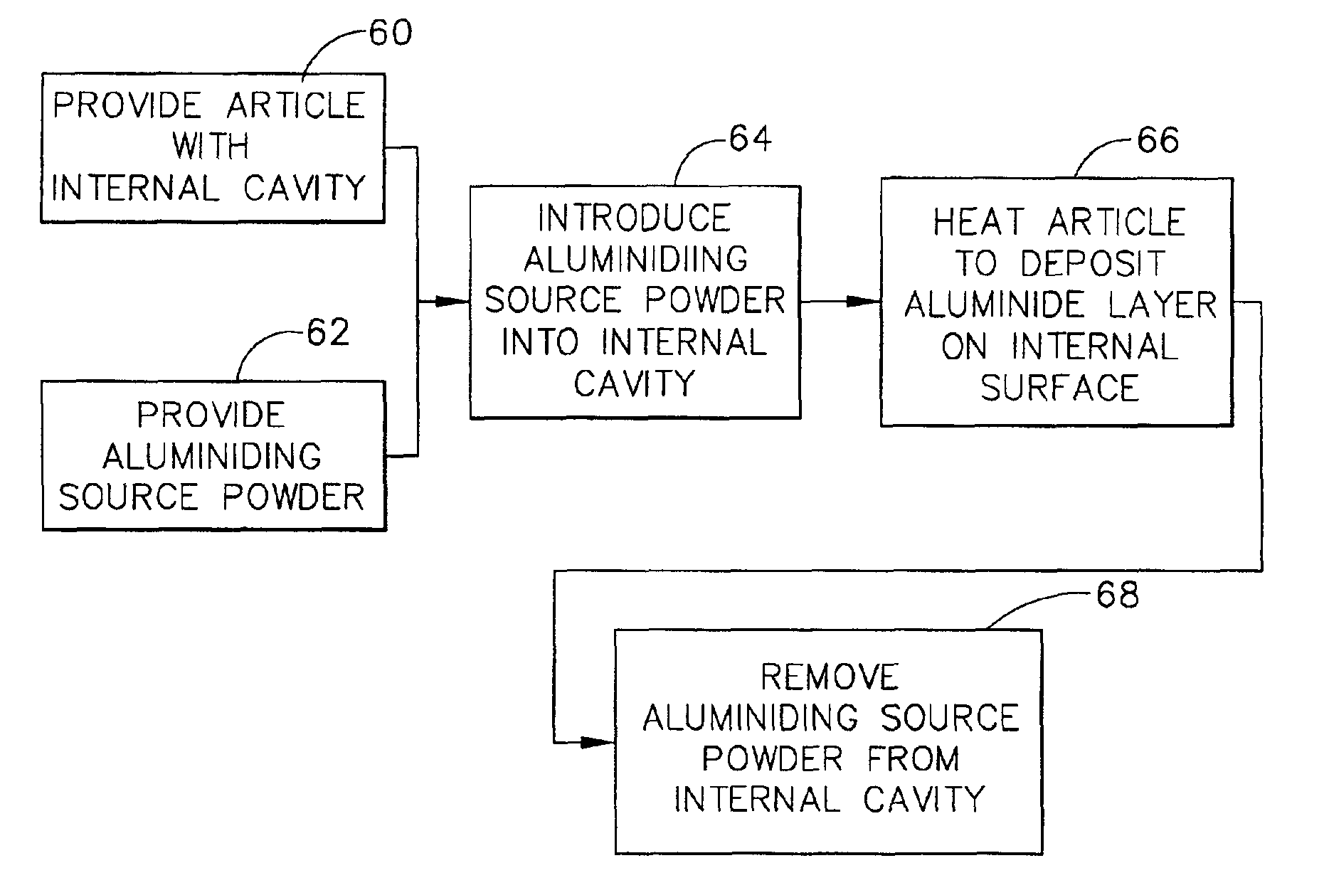
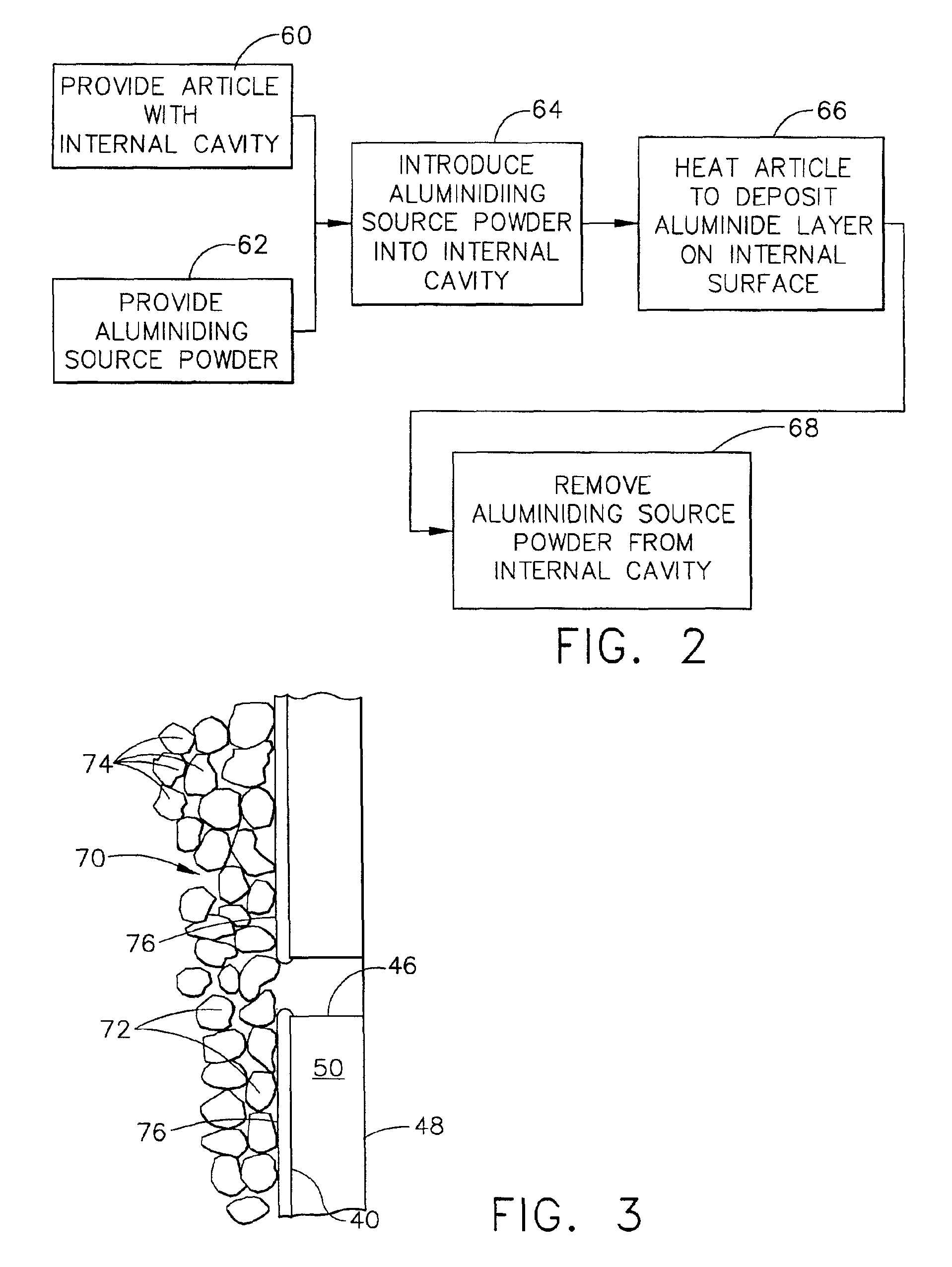
In current engines, the turbine vanes and blades are made of nickel-based superalloys, and can operate at temperatures of up to about 2150° F. These components are also subject to damage by oxidation and corrosive agents, as well as impact damage and erosion by particles entrained in the combustion gas stream.
As the operating temperatures have been pushed even further upwardly, it has been found that the internal surfaces of the internal cooling cavities experience oxidation and other degradation during service, particularly near the tip of the turbine blade.
However, the application of coatings to the internal surfaces poses some problems not found for external coatings, particularly because of the presence of the small-diameter outlets.
Existing external coating techniques, when applied to internal coating, and candidate internal coating techniques are not sufficient to achieve the necessary internal coatings.

Method used


Image

  • Dimensionally controlled pack aluminiding of internal surfaces of a hollow article
  • Dimensionally controlled pack aluminiding of internal surfaces of a hollow article
  • Dimensionally controlled pack aluminiding of internal surfaces of a hollow article

Examples


Embodiment Construction

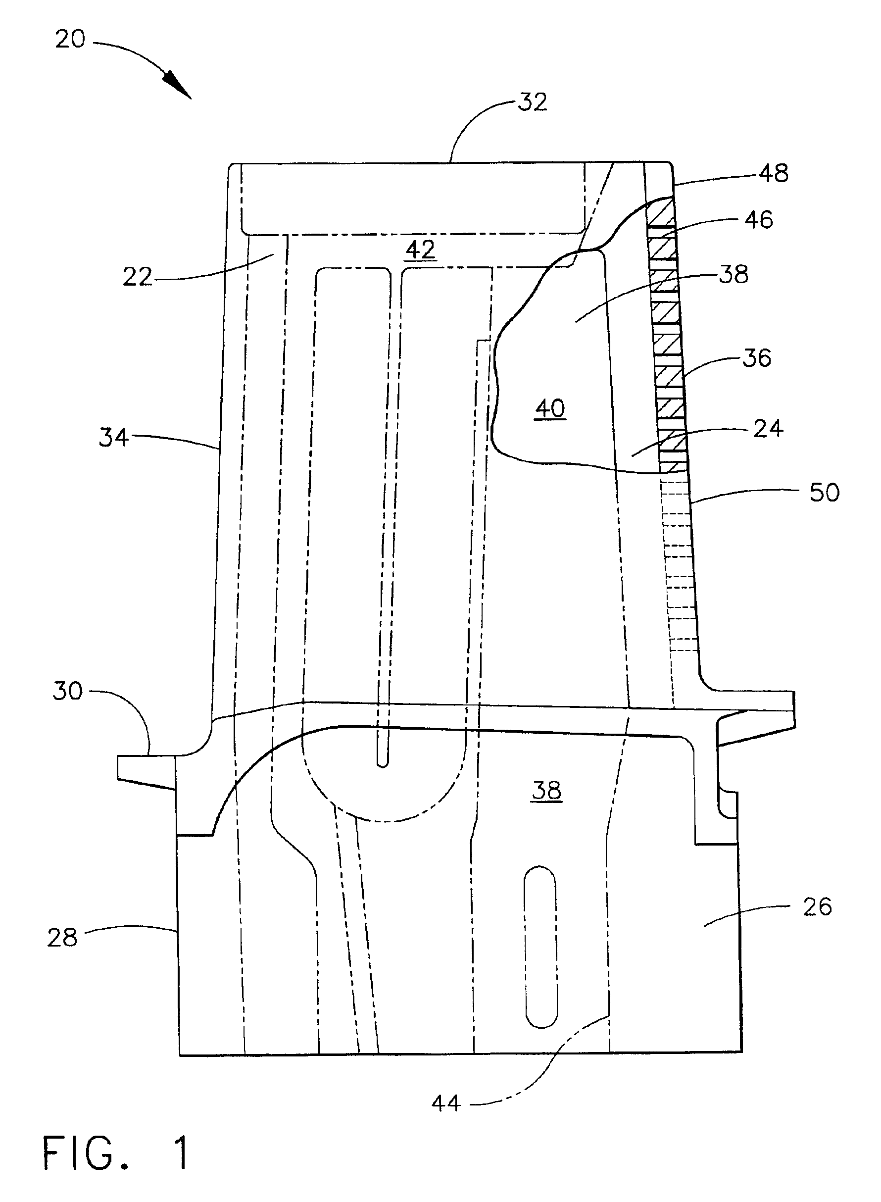
[0025]FIG. 1 depicts a hollow component 20 of a gas turbine engine, in this case a hollow gas turbine blade 22, with interior structure shown in phantom view. The gas turbine blade 22 is preferably formed of a nickel-base superalloy. The turbine blade 20 includes an airfoil 24 against which the flow of hot exhaust gas is directed. The turbine blade 20 is mounted to a turbine disk (not shown) by a dovetail shape 26 in a shank 28 of the gas turbine blade 22, which extends downwardly from the airfoil 24. The dovetail shape 26 engages a slot on the turbine disk (not shown) to mount the gas turbine blade 22 to the turbine disk. A platform 30 extends laterally outwardly from the area where the airfoil 24 is continuous with the shank 28. The gas turbine blade 22 may be described as having a tip end 32 opposite from the shank 28, a leading edge 34 that is first contacted by the hot exhaust gas, and a trailing edge 36.

[0026]As may be seen in the phantom view of FIG. 1, one or more internal c...


PUM

PropertyMeasurementUnit
Temperatureaaaaaaaaaa
Lengthaaaaaaaaaa

Abstract

An article such as a hollow gas turbine blade has an internal cavity therein with an inlet and outlet. The outlet has an outlet minimum transverse dimension of from about 0.009 inch to about 0.012 inch. An aluminiding source powder has a minimum particle size of greater than about 0.0015 inch and not greater than about 0.005 inch. The aluminiding source powder is a mixture of from about 5 to about 15 percent by weight of a metallic aluminum-containing powder and from about 85 to about 95 percent by weight of a ceramic powder. The aluminiding source powder is flowed into the internal cavity through the inlet, and the article is heated with the aluminiding source powder in the internal cavity to a temperature of from about 1750° F. to about 2000° F., and for a time of from about 2 hours to about 12 hours, to deposit an aluminum-containing coating on the internal surface of the internal cavity. The aluminiding source powder is thereafter removed from the internal cavity through the inlet.

Description

[0001]This invention relates to coating the internal surfaces of a hollow gas turbine component such as a hollow gas turbine blade and, more particularly, to aluminiding the internal surfaces using a pack process to achieve a precisely controlled coating thickness.BACKGROUND OF THE INVENTION[0002]In an aircraft gas turbine (jet) engine, air is drawn into the front of the engine, compressed by a shaft-mounted compressor, and mixed with fuel. The mixture is burned, and the hot combustion gases are passed through a turbine mounted on the same shaft. The flow of combustion gas turns the turbine by impingement against an airfoil section of the turbine blades and vanes, which turns the shaft and provides power to the compressor. The hot exhaust gases flow from the back of the engine, driving it and the aircraft forward.[0003]The hotter the combustion and exhaust gases, the more efficient is the operation of the jet engine. There is thus an incentive to raise the combustion and exhaust gas...

Claims


Application Information

Patent Timeline
IPC IPC(8): B05D7/22B21D53/78B23P15/02C23C10/48C23C10/50F01D5/28
CPCC23C10/48C23C10/50F01D5/286Y02T50/67Y10T29/49341F05D2300/21F05D2230/90F05D2300/121F05D2300/132Y02T50/671Y02T50/60
Inventor SHAH, ATUL NATVERLAL
Owner GENERAL ELECTRIC CO
Why Eureka
Try Eureka