
In situ thermal processing of a coal formation using a movable heating element

Inactive Publication Date: 2006-08-29
SHELL OIL CO
View PDF584 Cites 255 Cited by
  • Summary
  • Abstract
  • Description
  • Claims
  • Application Information

AI Technical Summary

Benefits of technology

[0028]One or more heat sources may be located within the formation such that superposition of heat produced from one or more heat sources may occur. Superposition of heat may increase a temperature of the selected section to a temperature sufficient for pyrolysis of at least some of the hydrocarbons within the selected section. Superposition of heat may vary depending on, for example, a spacing between heat sources. The spacing between heat sources may be selected to optimize heating of the section selected for treatment. Therefore, hydrocarbons may be pyrolyzed within a larger area of the portion. In this manner, spacing between heat sources may be selected to increase the effectiveness of the heat sources, thereby increasing the economic viability of a selected in situ conversion process for hydrocarbons. Superposition of heat tends to increase the uniformity of heat distribution in the section of the formation selected for treatment.
[0085]Cooling the formation may provide certain benefits such as increasing the strength of the rock in the formation (thereby mitigating subsidence), increasing absorptive capacity of the formation, etc.

Problems solved by technology

A significant number of coal formations are, however, not suitable for economical mining.
For example, mining coal from steeply dipping coal seams, from relatively thin coal seams (e.g., less than about 1 meter thick), and / or from deep coal seams may not be economically feasible.
The energy conversion efficiency of burning coal to generate electricity is relatively low, as compared to fuels such as natural gas.
Also, burning coal to generate electricity often generates significant amounts of carbon dioxide, oxides of sulfur, and oxides of nitrogen that are released into the atmosphere.
At present, however, there are still many coal formations from which hydrocarbons, hydrogen, and / or other products cannot be economically produced.

Method used


Image

  • In situ thermal processing of a coal formation using a movable heating element
  • In situ thermal processing of a coal formation using a movable heating element
  • In situ thermal processing of a coal formation using a movable heating element

Examples


Embodiment Construction

[0202]The following description generally relates to systems and methods for treating a coal formation, which may include, but is not limited to, humic and / or sapropelic coal. Such formations may be treated to yield relatively high quality hydrocarbon products, hydrogen, and other products.

[0203]As used herein, the word “coal” is generally defined to include naturally formed sedimentary rock or other rock that contains at least about 70% by volume of organic matter.

[0204]As used herein, “a method of treating a coal formation” may be used interchangeably with “an in situ conversion process for coal.”

[0205]“Hydrocarbons” are generally defined as molecules formed primarily by carbon and hydrogen atoms. Hydrocarbons may also include other elements, such as, but not limited to, halogens, metallic elements, nitrogen, oxygen, and / or sulfur.

[0206]“Kerogen” is generally defined as a solid, insoluble hydrocarbon that has been converted by natural degradation (e.g., by diagenesis) and that pri...


PUM


Abstract

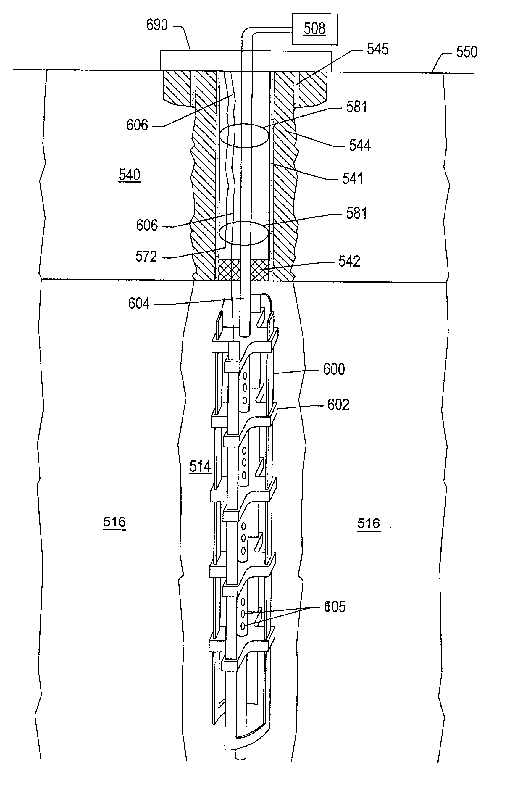
A coal formation may be treated using an in situ thermal process. A mixture of hydrocarbons, H2, and / or other formation fluids may be produced from the formation. Heat may be applied to the formation to raise a temperature of a portion of the formation to a pyrolysis temperature. Heat may be applied to the formation from heating elements positioned within wellbores. Portions of the heater elements may be free to move within the wellbores to inhibit failure of the heater elements due to thermal expansion.

Description

PRIORITY CLAIM[0001]This application claims priority to U.S. Provisional Application No. 60 / 199,215 entitled “In Situ Energy Recovery,” filed Apr. 24, 2000, U.S. Provisional Application No. 60 / 199,214 entitled “In Situ Energy Recovery From Coal,” filed Apr. 24, 2000, and U.S. Provisional Application No. 60 / 199,213 entitled “Emissionless Energy Recovery From Coal,” filed Apr. 24, 2000. The above-referenced provisional applications are hereby incorporated by reference as if fully set forth herein.BACKGROUND OF THE INVENTION[0002]1. Field of the Invention[0003]The present invention relates generally to methods and systems for production of hydrocarbons, hydrogen, and / or other products from coal formations. Certain embodiments relate to in situ conversion of hydrocarbons to produce hydrocarbons, hydrogen, and / or novel product streams from underground coal formations.[0004]2. Description of Related Art[0005]Hydrocarbons obtained from subterranean (e.g., sedimentary) formations are often ...

Claims


Application Information

Patent Timeline
IPC IPC(8): E21B43/24E21B43/243E21B43/30C09K8/592E21B36/00E21B36/04E21B41/00E21B43/247
CPCE21B36/001E21B36/04E21B41/0057E21B43/24E21B43/243E21B43/247E21B43/30E21B43/2401Y02C10/14Y02C20/40
Inventor DE ROUFFIGNAC, ERIC PIERREVINEGAR, HAROLD J.WELLINGTON, SCOTT LEEKARANIKAS, JOHN MICHAELBERCHENKO, ILYA EMILSTEGEMEIER, GEORGE LEOZHANG, ETUANFOWLER, THOMAS DAVIDRYAN, ROBERT CHARLES
Owner SHELL OIL CO
Learn More