Method and apparatus for membrane separation of air into nitrogen and oxygen elements for use in internal combustion engines

a technology of nitrogen and oxygen elements, which is applied in the direction of separation processes, machines/engines, and membranes, can solve the problems of engine overheating, engine emissions, and carbon monoxide is one of the most dangerous of the combustion process pollutants, so as to reduce emissions and improve the performance of the internal combustion engine

Inactive Publication Date: 2006-09-05
WORLD AIR ENERGY CORP
View PDF7 Cites 29 Cited by
  • Summary
  • Abstract
  • Description
  • Claims
  • Application Information

AI Technical Summary

Benefits of technology

[0008]The present invention comprises a method and apparatus for reducing the emissions and improving the performance of an internal combustion engine. An input air stream is separated at least in part into an oxygen-enriched air stream and a nitrogen-enriched air stream. The nitrogen-enriched air stream is received by a holding chamber. The oxygen-enriched air and a combustible fuel are provided to a combustion chamber of the internal combustion engine and a combustion process is initiated. After a predefined time delay, a volume of nitrogen-enriched air is provided from the holding chamber to the combustion chamber to be used during the rest of the combustion process.

Problems solved by technology

However, internal combustion engines produce emissions from the combustion process which include a number of pollutants whose presence are undesirable in the environment.
Carbon monoxide is a colorless, odorless, and toxic gas, and is one of the most dangerous of the combustion process pollutants.
Particulate matter is a major source of visible urban air pollution such as soot and haze.
However, oxygen-enrichment of the combustion process results in an undesirable change in NOx production, as well as an increase in combustion temperatures, which can cause engine overheating.
However, U.S. Pat. No. 5,636,619 does not offer a solution to the problem of engine overheating caused by oxygen-enrichment of intake air.
However, U.S. Pat. No. 5,640,845 also does not offer a solution to the problem of engine overheating caused by oxygen-enrichment of intake air.

Method used


Image

  • Method and apparatus for membrane separation of air into nitrogen and oxygen elements for use in internal combustion engines
  • Method and apparatus for membrane separation of air into nitrogen and oxygen elements for use in internal combustion engines
  • Method and apparatus for membrane separation of air into nitrogen and oxygen elements for use in internal combustion engines

Examples


Embodiment Construction

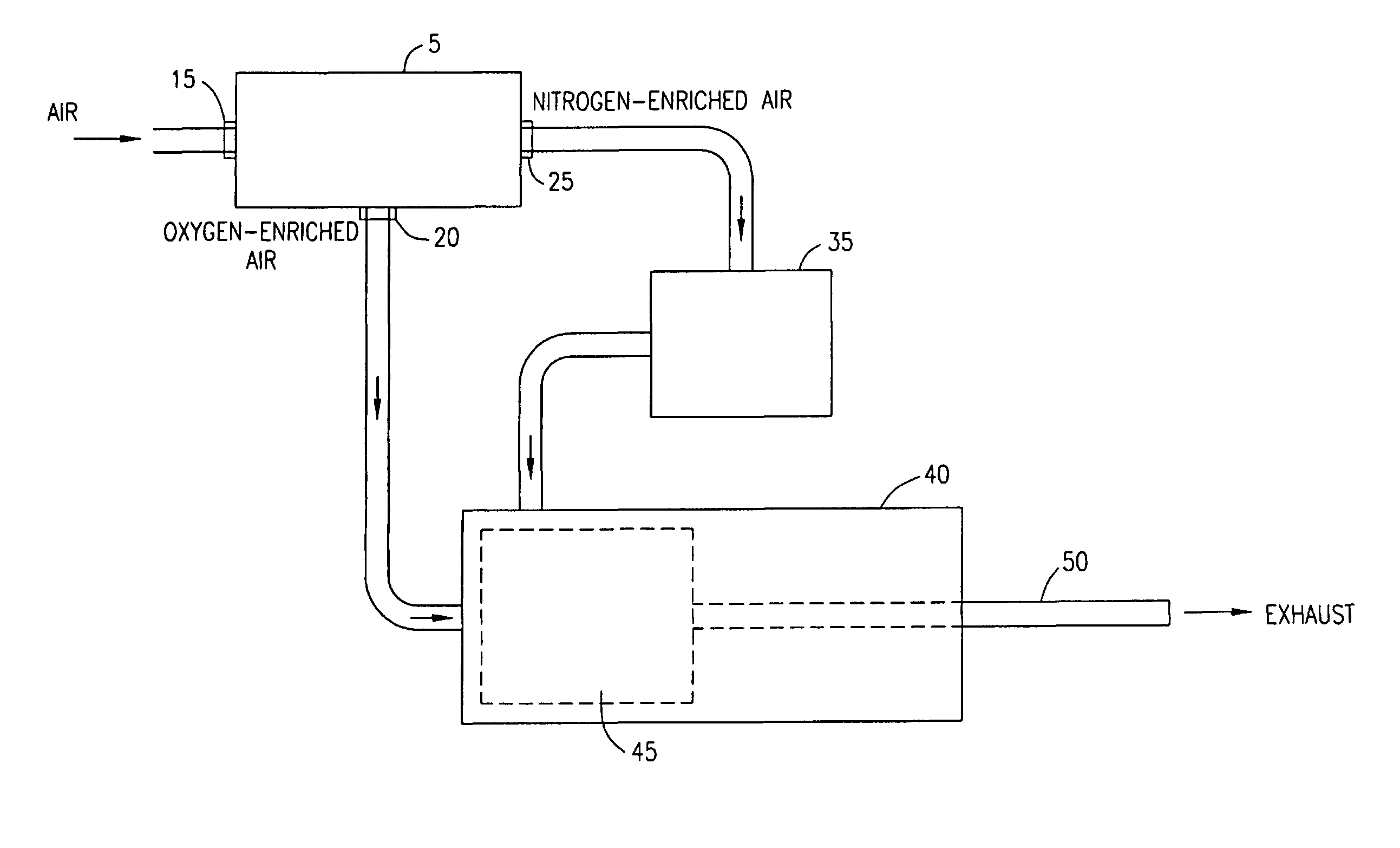
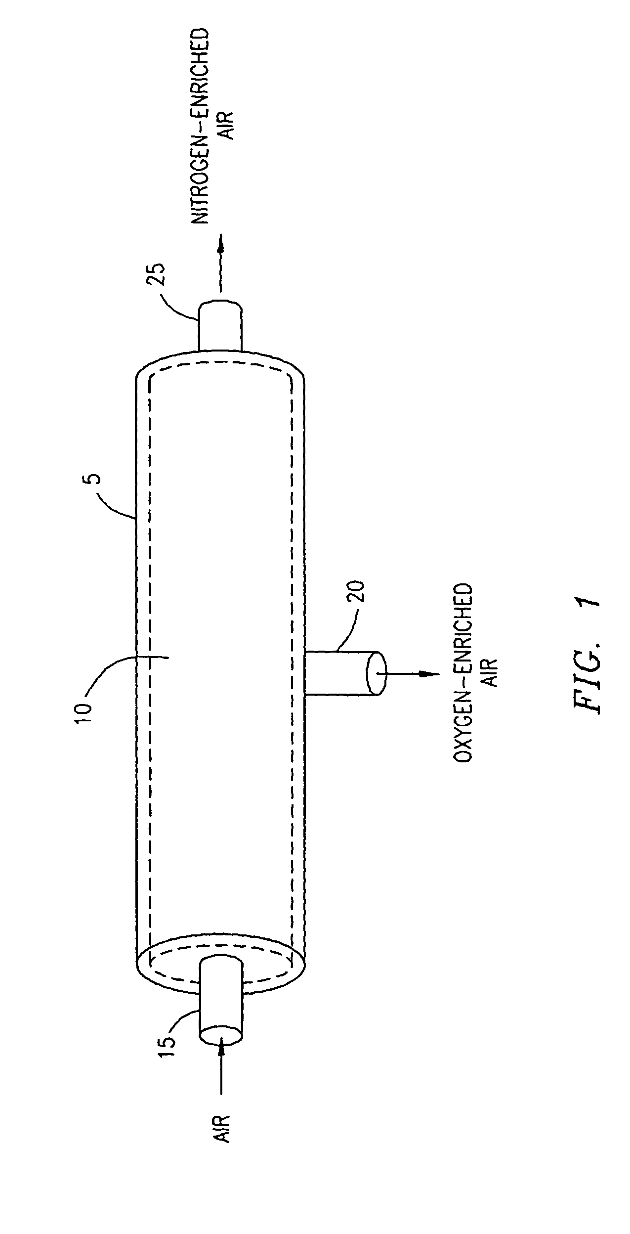
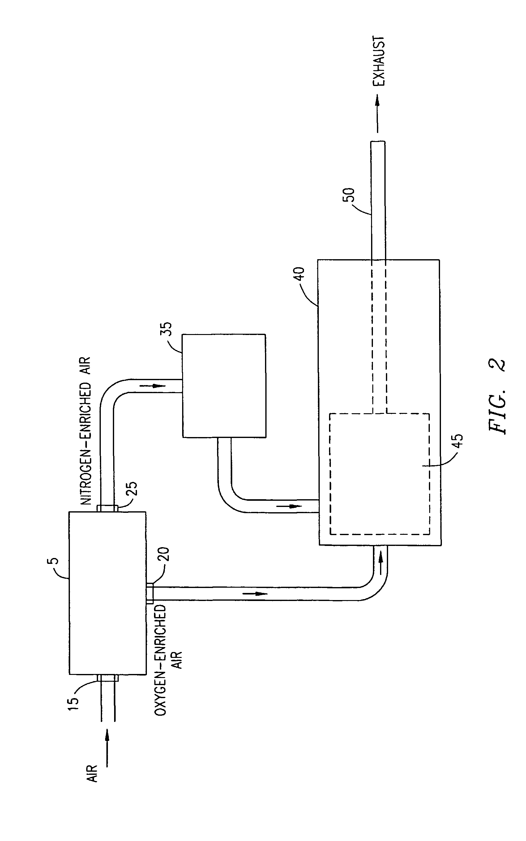
[0013]Reference is now made to the Drawings wherein like reference characters denote like or similar parts throughout the various Figures. Referring now to FIG. 1, a membrane 5 for the separation of air into nitrogen and oxygen elements in accordance with the principles of the present invention is illustrated. The membrane 5 functions to separate air directed into the membrane 5 into oxygen-enriched air streams and nitrogen-enriched air streams. The membrane 5 contains an inner membrane material 10, which through a process of selective permeation or solution-diffusion separates the air directed through the membrane material 10 into an oxygen-enriched air stream and a nitrogen-enriched air stream. This process can be accomplished due to the fact that oxygen has a higher solubility through the inner membrane material 10 than that of nitrogen. Typically, the membrane material 10 is composed of a bundle of hollow polymer fibers which selectively allow oxygen molecules to diffuse through...


PUM


Abstract

A method and apparatus for reducing the emissions and improving the performance of an internal combustion engine (40). An input air stream is separated into an oxygen-enriched air stream and a nitrogen-enriched air stream. The nitrogen-enriched air stream is received by a holding chamber (35). The oxygen-enriched air and a combustible fuel are provided to a combustion chamber (45) of the internal combustion engine (40) and a combustion process is initiated. After a predefined time delay, a volume of nitrogen-enriched air is provided from the holding chamber (35) to the combustion chamber (45) to be used during the rest of the combustion process.

Description

BACKGROUND OF THE INVENTION[0001]1. Technical Field of the Invention[0002]This invention relates to a method and system for reducing emissions and improving performance of an internal combustion engine by providing oxygen-enriched air and nitrogen-enriched air to a combustion chamber.[0003]2. Description of Related Art[0004]The purpose of an internal combustion engine is to convert the chemical energy of fuel into the mechanical energy of motion using a process of combustion. As is known, internal combustion engines are used extensively in a variety of machines including mobile vehicles, or for other purposes, such as power generation. However, internal combustion engines produce emissions from the combustion process which include a number of pollutants whose presence are undesirable in the environment. As a result, numerous regulations have been implemented by various government bodies requiring reductions in these pollutants. The primary pollutants produced by internal combustion ...

Claims


Application Information

Patent Timeline
Patent Type & Authority Patents(United States)
IPC IPC(8): F02B41/00B01D53/22F02B47/06F02D19/12F02M25/12
CPCB01D53/22B01D63/02F02B47/06F02D19/12F02M25/12F02B47/00B01D2313/18Y02T10/121Y02T10/12
Inventor DAVIDSON, JAMES G.
Owner WORLD AIR ENERGY CORP
Why Eureka
Try Eureka