Variable frequency PWM controller circuit

a controller circuit and variable frequency technology, applied in pulse generators, pulse techniques, instruments, etc., can solve the problems of driving the main switch loss, low loss of control circuits, and high switching loss, and achieve the effects of low frequency, short on time, and high frequency

Active Publication Date: 2006-09-12
DELTA ELECTRONICS INC
View PDF6 Cites 40 Cited by
  • Summary
  • Abstract
  • Description
  • Claims
  • Application Information

AI Technical Summary

Benefits of technology

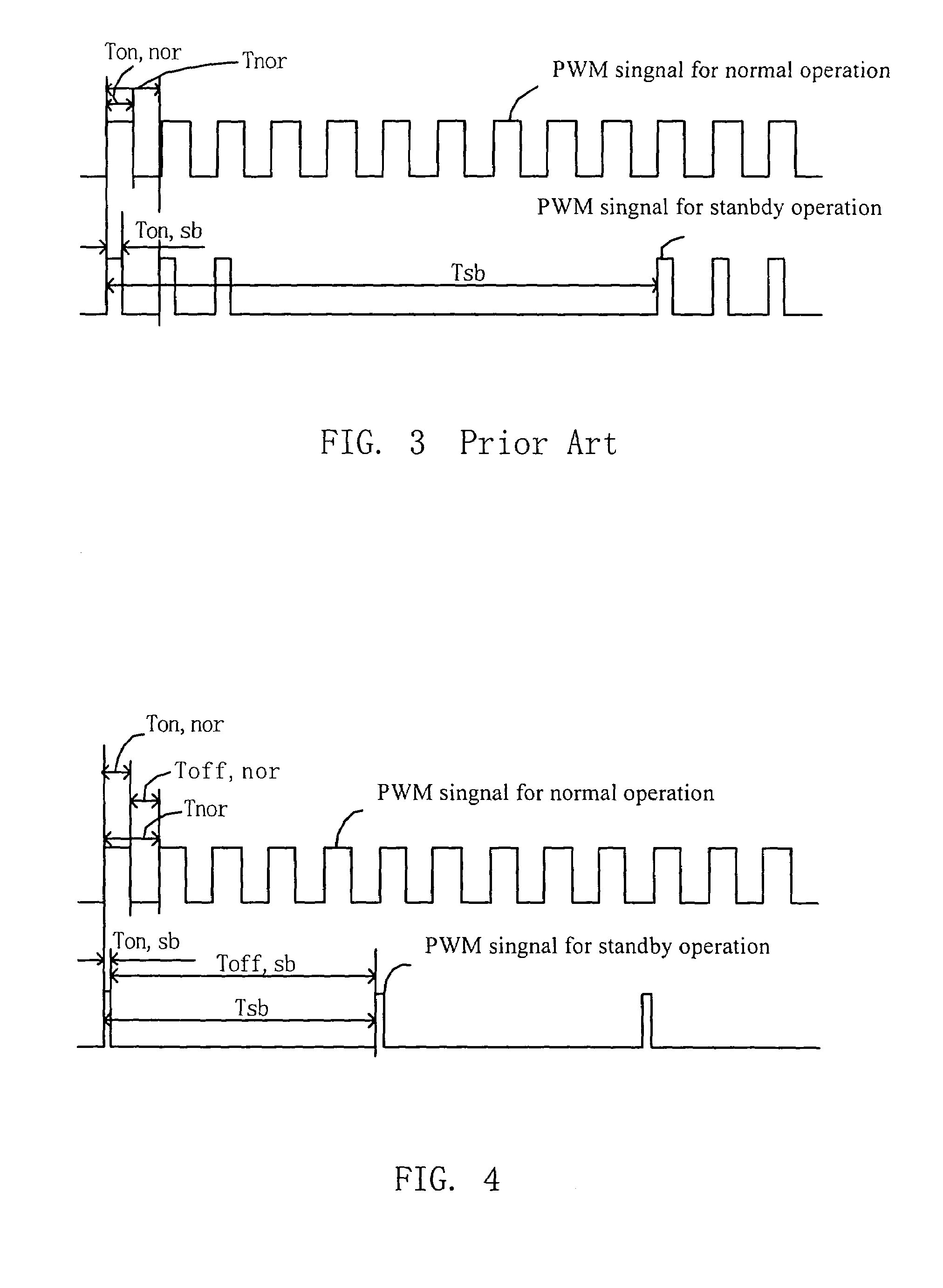
[0010]A new PWM signal generating scheme is presented, as shown in FIG. 4. The on time and the off time of the PWM signal are regulated simultaneously according to the scheme. Each of the generated PWM signals will have relatively a very short on time and a very low frequency in the standby operation mode, and have relatively a high frequency and a long on time in the normal operation mode, thus the aforementioned ripple and noise can be eliminated while the relatively low standby loss feature is maintained.
[0011]In more details, each of the PWM signals will have relatively a long on time Ton,nor and a short switching period Tnor in the normal operation mode according to the present invention. Thus, the duty cycle Dnor, which is equal to Ton,nor / Tnor, is relatively high and the switching frequency fnor, which is equal to 1 / Tnor, is relatively high too. These relatively high duty cycle and high switching frequency are advantageous to the relatively high power density and high efficiency design of the power converter.
[0012]As the load decreasing, the on time of the PWM signal is decreased while the off time of the PWM signal is increased. As a result, the on time Ton,sb of the PWM signal is reduced to a relatively low value, the off time Toff,sb and thus the switching period Tsb are increased to a relatively high value in the standby operation mode. Therefore, relatively very low duty cycle and very low switching frequency can be achieved in the standby operation mode of the power converter, wherein relatively low standby loss, low output voltage noise and no audible noise are realized simultaneously.
[0015]The present invention allows relatively a low duty cycle and a low frequency operation, which makes a power converter operate with relatively low ripple, low noise and low standby loss. This is a significant improvement over the prior art.

Problems solved by technology

Meanwhile, the control circuit dissipates relatively low loss due to relatively low frequency operation.
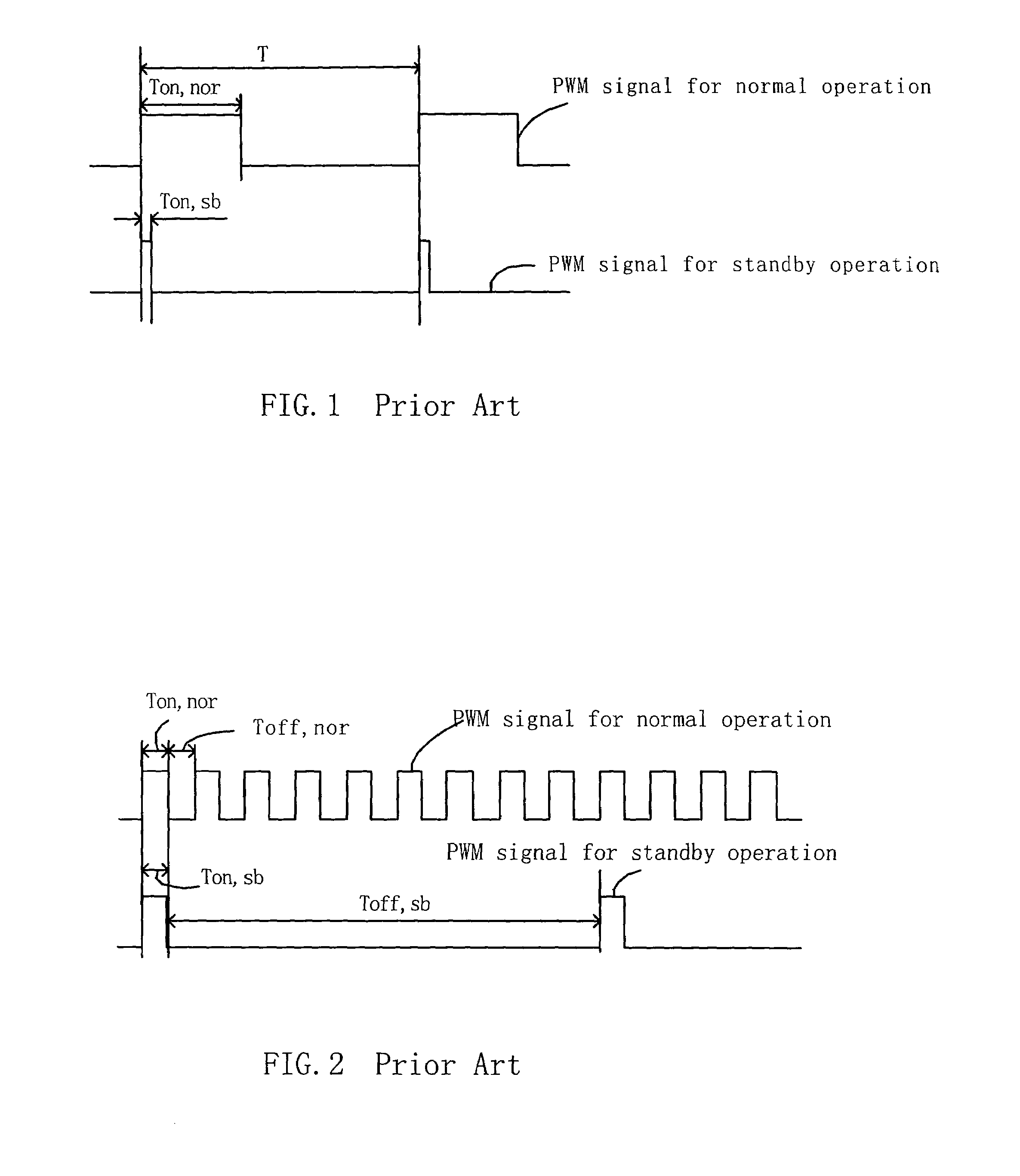
In the standby operation mode, the power circuit always operates with relatively a very short time Ton,sb and thus a very small duty cycle, but the switching frequency is still high as normal operation, resulting in relatively much switching loss and driving loss of the main switch and much power loss of the controller which are the major parts of the standby loss.
Therefore, the standby loss of the converter will be relatively high.
One drawback of this control method is that the conversion power at each switching cycle will be relatively high due to the constant on time of the PWM signal in the standby operation mode.
But there are problems with this control mode also.
In the standby operation mode, the conversion power of the converter during the several continuous switching periods with PWM pulses will be relatively high, resulting in relatively high output voltage noise.
This will also introduces the audible noise to the converter.

Method used


Image

  • Variable frequency PWM controller circuit
  • Variable frequency PWM controller circuit
  • Variable frequency PWM controller circuit

Examples


Embodiment Construction

[0025]Although this invention is susceptible to embodiments of many different forms, a preferred embodiment will be described and illustrated in detail herein. The present disclosure exemplifies the principle of the invention and is not being considered a limitation to the broader aspects of the invention to the particular embodiment as described.

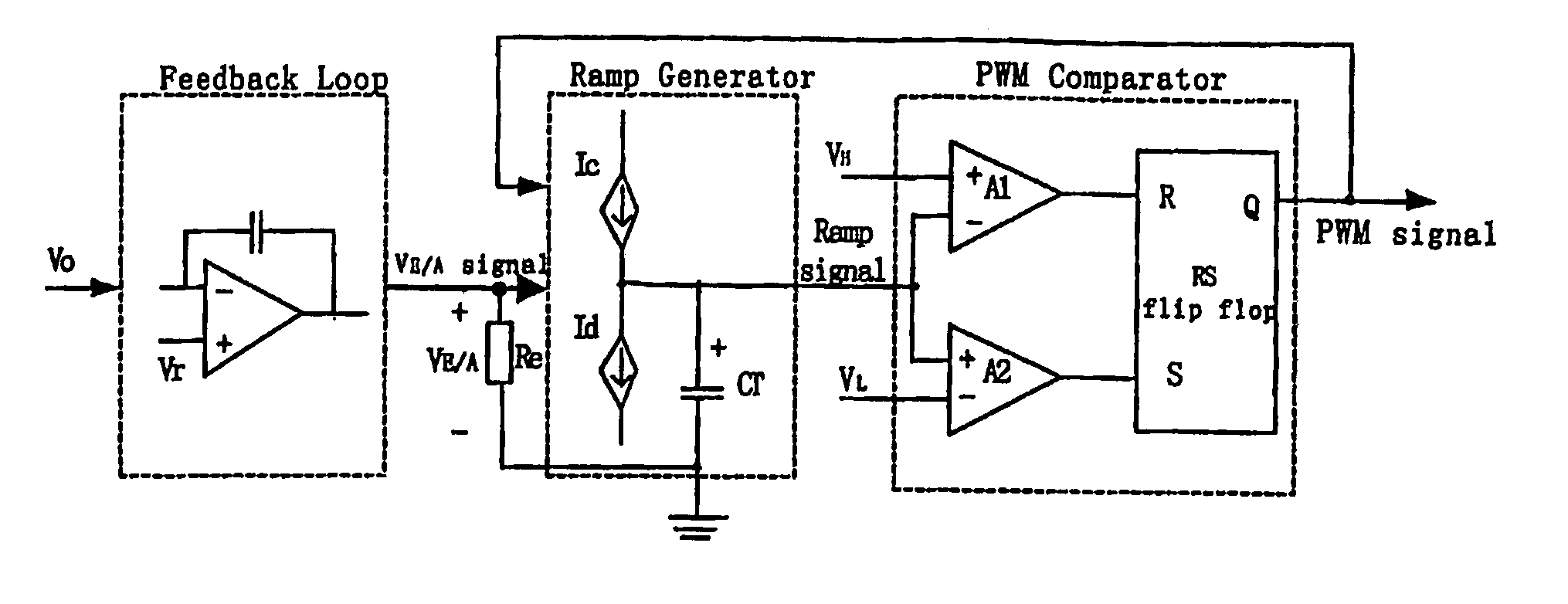
[0026]In FIG. 5, a circuit diagram to realize the VF PWM control scheme according to the present invention is shown. The overall circuit of the invention has three parts including a feedback loop, a synchronous signal generator and a PWM comparator.

[0027]The output voltage is input to the feedback loop which in-turn outputs an error-amplified voltage VE / A. The VE / A signal is firstly input to a synchronous signal generator, which includes a VCO (Voltage Control Oscillator) and selectively includes a pulse generator, which is an optional component coupled to the VCO and can be omitted without damping the functions of the synchronous generator...


PUM


Abstract

The present invention discloses a circuit that generates a variable frequency pulse width modulation (VF PWM) signal. Different from the conventional PWM controller, the frequency and duty cycle of the output PWM signal vary with the error-amplified voltage of the feedback loop simultaneously in this invention. The higher the error-amplified voltage of the feedback loop is, the lower the duty cycle with lower frequency will be. A very low duty cycle PWM signal can be generated stably while its frequency is very low.

Description

FIELD OF THE INVENTION[0001]The present invention relates to switching mode power supplies, and more specifically to a varied frequency pulse width modulation controller for low standby loss solution.BACKGROUND OF THE INVENTION[0002]The trend in the design of switching mode power supplies has been toward relatively low power loss, low ripple and low noise under light load condition, especially for those widely used adaptors for notebooks, computers, and chargers for mobile telecommunication apparatus. This kind of power supplies frequently operates under a light or zero load condition, which is named as the standby operation mode.[0003]A flyback converter is the most commonly used topology for this application with pulse width modulation (PWM) control for the output regulation. To achieve relatively very low power loss under light or open load condition, it is the key factor to control the power stage to operate at a relatively very low switching frequency to decrease the switching ...

Claims


Application Information

Patent Timeline
Patent Type & Authority Patents(United States)
IPC IPC(8): H03F3/38H02M3/156H03K3/0231
CPCH02M3/156Y02B70/16H03K3/0231H02M2001/0032Y02B70/10H02M1/0032
Inventor GAN, HONGJIANWANG, BOZHANG, ALPHA J.
Owner DELTA ELECTRONICS INC
Why Eureka
Try Eureka