Polytetrafluoroethylene fiber and method for manufacturing the same

a technology of polytetrafluoroethylene and fibers, which is applied in the direction of transportation and packaging, synthetic resin layered products, and other chemical processes, can solve the problems of high manufacturing cost of ptfe by this method, low strength of fibers obtained, and inability to produce fibers by a generally adopted method such as extrusion spinning of molten resins and resin solutions, etc., to achieve uniform fineness, high production yield, and small average fineness

Active Publication Date: 2006-09-19
YEU MING TAI CHEM INDAL
View PDF20 Cites 27 Cited by
  • Summary
  • Abstract
  • Description
  • Claims
  • Application Information

AI Technical Summary

Benefits of technology

[0008]Therefore, with the foregoing in mind, it is an object of the present invention to provide a PTFE fiber in which single fibrils have a small average fineness and have uniform fineness and to provide a method for manufacturing the PTFE fiber. Furthermore, it is another object of the present invention to provide a PTFE fiber in which a fiber can be manufactured from the overall width of a film, that has a high production yield and whose branch structure is uniform and stable and to provide a method for manufacturing the PTFE fiber.

Problems solved by technology

Since PTFE resins have a relatively high melting viscosity and are not dissolved by most solvents, fibers cannot be produced by a generally adopted method such as extrusion spinning of molten resins and resin solutions.
However, the manufacturing cost of the PTFE by this method is high, whereas the strength of the fiber obtained is low, and therefore the strength of a product obtained by processing this fiber as a raw material also is low.
However, this method has a difficulty in maintaining a width of the tape obtained by slitting uniformly along the lengthwise direction.
Also, there exists a problem that an end portion of the tape tends to be a fibril.
For these reasons, there exists another problem that the fiber may break partially during the step of stretching the tape to a high degree.
According to this method, however, the length of the obtained PTFE fibers mostly is not more than 150 mm, and it is difficult to obtain a PTFE filament.
According to this method, however, the density of the obtained PTFE fibers has a high specific gravity exceeding 2.15 g / cm3, thus making it difficult to obtain a light-weight final product.
In the case where the afore-mentioned PTFE oriented film is supplied to a revolving pin roll so as to produce a PTFE fiber, problems occur such as difficulty in making a single fibril thinner, nonuniform fineness and the occurrence of many losses from the end portions of the film supplied.
Furthermore, a network structure of the filament is not uniform and therefore a branch structure of a branched PTFE short fiber obtained by cutting the filament also is not uniform and not stable.

Method used


Image

  • Polytetrafluoroethylene fiber and method for manufacturing the same
  • Polytetrafluoroethylene fiber and method for manufacturing the same
  • Polytetrafluoroethylene fiber and method for manufacturing the same

Examples


working examples

[0058]The following describes the present invention more specifically by way of working examples.

(Manufacturing of PTFE Original Film)

[0059]To 80 mass parts of PTFE fine powders obtained by an emulsion polymerization method, 20 mass parts of naphtha was mixed. This mixture was subjected to paste extrusion through a die with an angle of 60° under the condition of RR of 80:1 so as to obtain a circular bar with a diameter of 17 mm. This extruded article was rolled between a pair of rolls with a diameter of 500 mm, followed by the removal of the naphtha at a temperature of 260° C. The thus obtained PTFE film had a length of about 250 m, a film thickness of 0.2 mm and a width of about 260 mm.

working example 1

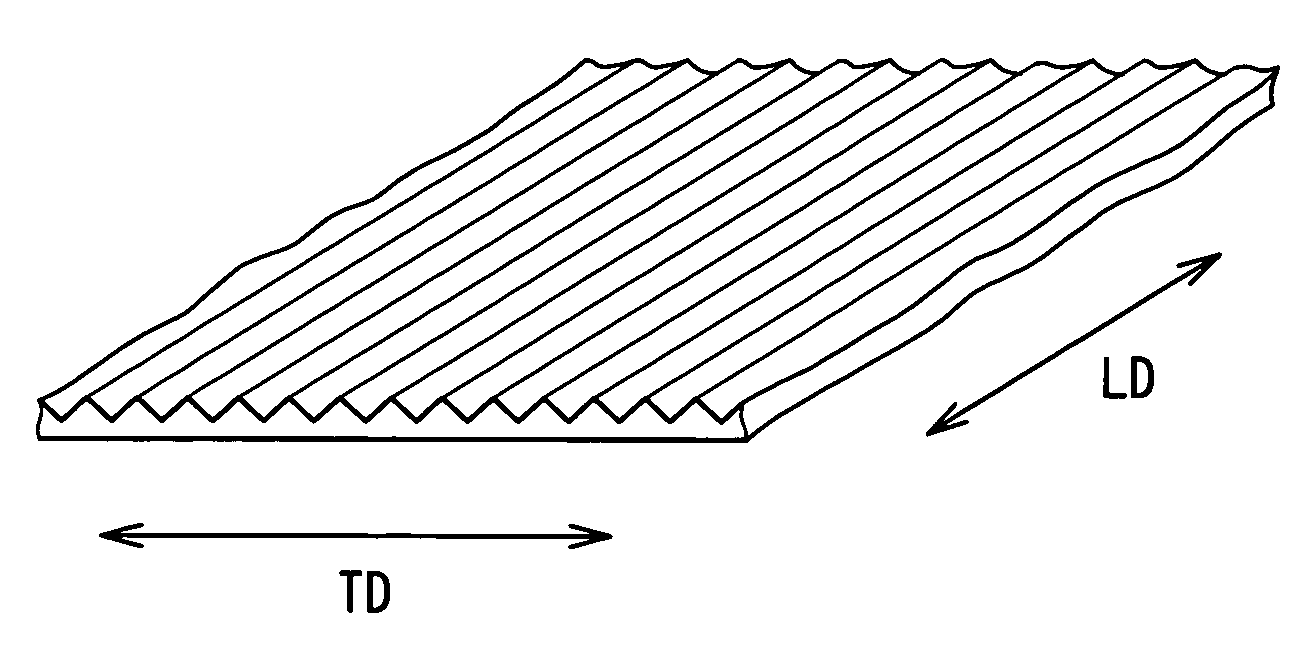
[0060]The PTFE original film obtained by the above-stated process was uniaxially stretched by 12 times in the lengthwise direction. Thereafter, this film was heat-treated at 380° C. for 3 seconds. Thereby, a baked film of 0.2 mm in film thickness and 260 mm in width was obtained. Then, by using the emboss roll having the emboss pattern shown in FIG. 3A and the apparatus of FIG. 4, a zigzag pattern was given to the PTFE film, the zigzag pattern having a pitch interval X between a crest and an adjacent crest of 0.5 mm, a vertical interval Y of 0.6 mm and a zigzag angle θ of 45°.

[0061]The linear pressure of the emboss roll during the emboss processing was 0.8 Kg / cm. The embossing was applied continuously in the lengthwise direction and in the width direction and all over the film.

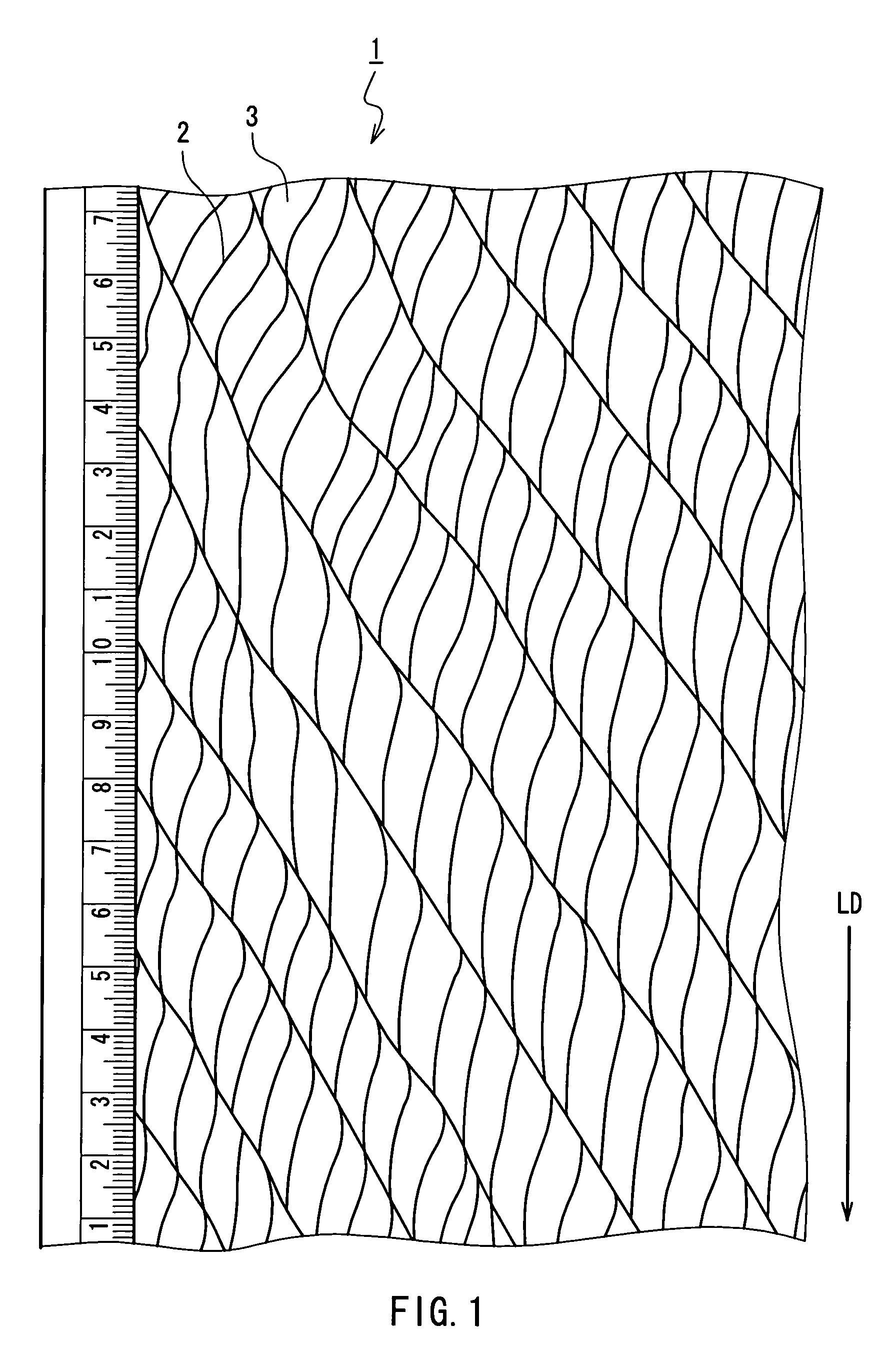
[0062]Next, the PTFE film was fed to a revolving roll with needles so as to slit the film to be opened, whereby a PTFE filament having a network structure was obtained, the network structure being made up of r...

working example 2

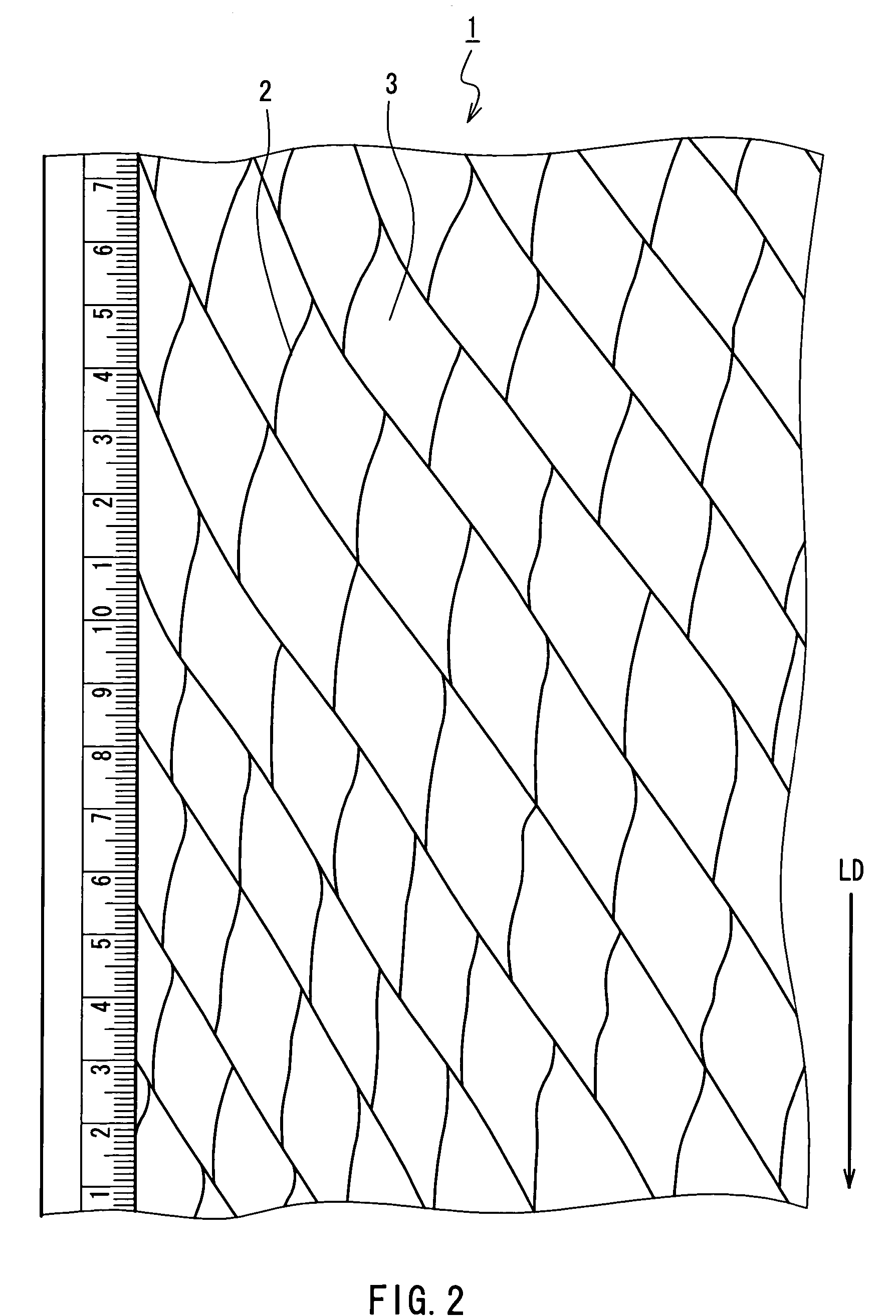
[0067]An original film was uniaxially stretched by 9 times in its lengthwise direction, and other conditions were the same as those in Working Example 1 so as to conduct a heat treatment, embossing and opening of the film. Thereby, a PTFE filament having a regular network structure was obtained.


PUM

PropertyMeasurementUnit
thicknessaaaaaaaaaa
thicknessaaaaaaaaaa
densityaaaaaaaaaa

Abstract

A polytetrafluoroethylene (PTFE) fiber includes a filament obtained by partially slitting an oriented PTFE film in a lengthwise direction of the film. Emboss processing is conducted linearly along the lengthwise direction of the film and like a zigzag shape or a convexo-concave shape in a width direction of the film, followed by slitting, whereby the filament includes a network structure in which single fibrils that are opened partially are arranged regularly. A PTFE short fiber is obtained by cutting the above filament and includes a branch structure. Thereby, a PTFE fiber with a small average fineness of single fibrils, a uniform fineness and a single-peak distribution with the peak at a center of fineness and with a high production yield and uniform and stable branch structure can be provided and a method for manufacturing the PTFE fiber can be provided.

Description

[0001]This is a Continuation-in-part of U.S. patent application Ser. No. 10 / 958,716, filed Oct. 4, 2004 now abandoned.FIELD OF THE INVENTION[0002]The present invention relates to polytetrafluoroethylene (PTFE) fibers and a method for manufacturing the same.BACKGROUND OF THE INVENTION[0003]Since PTFE resins have a relatively high melting viscosity and are not dissolved by most solvents, fibers cannot be produced by a generally adopted method such as extrusion spinning of molten resins and resin solutions. Therefore, various specific manufacturing methods have been adopted conventionally. U.S. Pat. No. 2,772,444 proposes a method for manufacturing a PTFE fiber by emulsion spinning of a mixed solution of an aqueous dispersion solution of PTFE fine particles and viscose, followed by sintering of the PTFE at high temperatures to remove the viscose by thermal decomposition. However, the manufacturing cost of the PTFE by this method is high, whereas the strength of the fiber obtained is lo...

Claims


Application Information

Patent Timeline
Patent Type & Authority Patents(United States)
IPC IPC(8): D01F6/00D02G3/00D02G3/06
CPCD02G3/06Y10T428/2973Y10S264/47Y10T428/2913Y10T428/2978Y10T428/2395Y10T428/3154Y10T428/31544
Inventor HUANG, JAMESCHOU, CHIN-CHUNCHOU, CHIN-CHACHEN, SHIA-CHUNGKUO, WEN-IHUANG, LEI-TI
Owner YEU MING TAI CHEM INDAL
Why Eureka
Try Eureka