Surface acoustic wave device, and mobile communication device and sensor both using same

a surface acoustic wave and sensor technology, applied in piezoelectric/electrostrictive/magnetostrictive devices, piezoelectric/electrostriction/magnetostriction machines, electrical apparatus, etc., can solve the problems of propagation loss produced by propagating the lsaw, lowering the manufacturing yield rate of the saw device, and achieving excellent steep characteristics , low loss, and small loss

Active Publication Date: 2006-09-19
SKYWORKS PANASONIC FILTER SOLUTIONS JAPAN
View PDF10 Cites 29 Cited by
  • Summary
  • Abstract
  • Description
  • Claims
  • Application Information

AI Technical Summary

Benefits of technology

[0029]The SAW device of the present invention with the foregoing structure includes the piezoelectric substrate made of the LT single-crystal, and this substrate has a cut-face cut out along the following orientation. With respect to the X-axis of the LT single-crystal, the crystal is rotated along the direction from the Y-axis to the Z-axis by an angle of not less than 26° and not more than 50°. The substrate also has characteristics that can excite the leaky surface acoustic wave (LSAW). When a SAW device using the conventional LSAW and the SAW device of the present invention are formed together on one chip, i.e., a SAW device of a two-device in one-chip is formed, the structure discussed above allows both of the SAW devices to produce low losses and have excellent steep characteristics.
[0030]The SAW device of the present invention with the foregoing structure has a piezoelectric substrate made of single-crystal of LiNbO3 (LN single-crystal). When a SAW device using the conventional LSAW and the SAW device of the present invention are formed together on one chip, i.e. a SAW device of a two-device in one-chip is formed, this structure allows for producing excellent characteristics.
[0031]The SAW device of the present invention with the foregoing structure includes the piezoelectric substrate made of LN single-crystal. This substrate has a cut-face cut out along the following orientation. With respect to the X-axis of the LN single-crystal, the c

Problems solved by technology

Those filters are required to have low loss in the pass-band, highly attenuate signals in the rejection band, and yet, have steep filter characteristics.
This means that the pattern width of the IDT electrodes should be extremely narrow, which results in lowering the manufacturing yield rate of the SAW devices.
As a result, the propagation loss produced by propagating the LSAW cannot be neglected.
As a result, a structure of two filters in one chip, where two SAW filters having different frequencies are formed on one chip, encounters the following problem.
Thus, it is

Method used


Image

  • Surface acoustic wave device, and mobile communication device and sensor both using same
  • Surface acoustic wave device, and mobile communication device and sensor both using same
  • Surface acoustic wave device, and mobile communication device and sensor both using same

Examples


exemplary embodiment 1

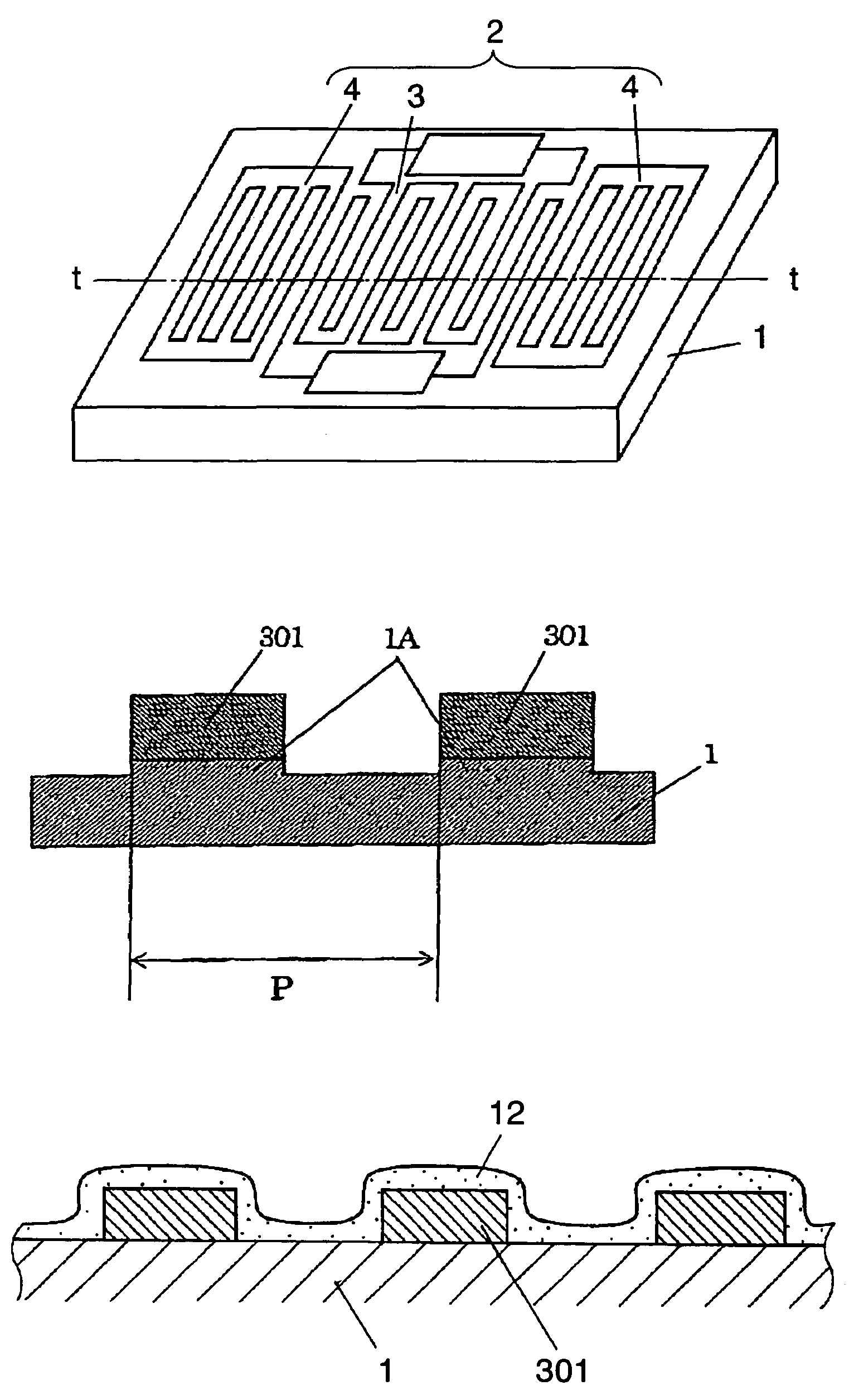
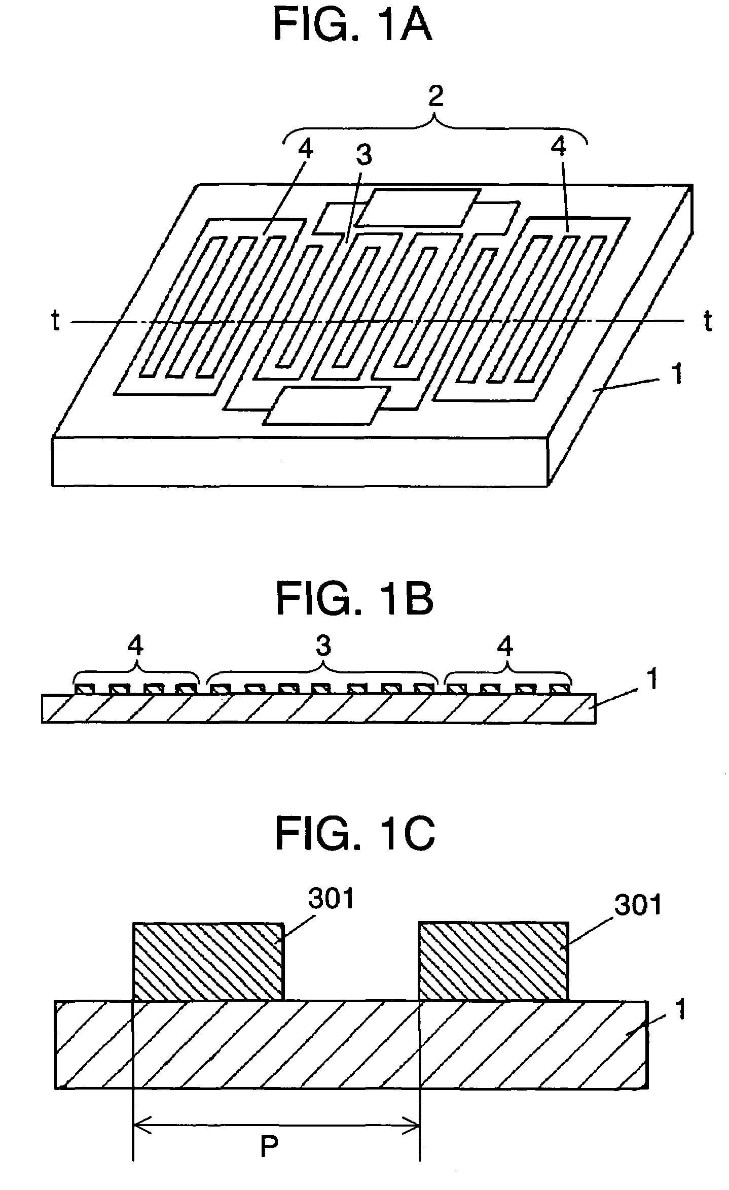
[0077]FIG. 1A shows a perspective view of a 1-port SAW resonator produced as an example of a SAW device in accordance with the first exemplary embodiment of the present invention. SAW resonator 2 is formed on piezoelectric substrate 1, and SAW resonator 2 is formed of IDT electrode 3 and reflector 4. FIG. 1B shows a sectional view taken along the line t-t of FIG. 1A. FIG. 1C shows an enlarged sectional view of one cycle of the IDT electrode, and the sectional view illustrates that finger-electrodes 301 are formed on substrate 1 at a given pitch “p”.

[0078]In this embodiment, an LT substrate of 39° Y-cut and on which the SAW propagates along the X-axis (hereinafter referred to as a 39° Y-XLT substrate) is used as piezoelectric substrate 1. A phase velocity “vb” of the slow shear wave that propagates on substrate 1 is 3350.8 m / s. The electrodes of SAW resonator 2 formed on piezoelectric substrate 1 are made of Al—Cu alloy, namely, Cu is added to Al. The electrodes of the SAW resonator ...

exemplary embodiment 2

[0096]A ladder SAW filter is produced as an example of the SAW device in accordance with the second exemplary embodiment of the present invention. FIG. 7A shows a perspective view illustrating a structure of this SAW filter. FIG. 7B shows a circuit diagram of this SAW filter. As FIG. 7B illustrates, the SAW filter comprises five SAW resonators 5 coupled in series, and two SAW resonators 6 coupled in parallel. Resonators 5 in series comprise IDT electrodes 7 and reflectors 9 disposed on both sides of electrodes 7. On the other hand, resonators 6 comprise IDT electrodes 8 and reflectors 10 disposed on both sides of electrodes 8. The film thickness and the pattern of the respective electrodes are set such that the center frequency becomes 836 MHz and the bandwidth becomes 25 MHz.

[0097]In this embodiment, a LT substrate of 42° Y-cut and X-propagation (hereinafter referred to as a LT42° substrate) is used as piezoelectric substrate 11. A slow shear wave propagating on this substrate 11 h...

exemplary embodiment 3

[0104]In this third embodiment, a 1-port SAW resonator similar to that used in the first embodiment is used as a SAW device. Samples 3–6 employ a LT 36° substrate as piezoelectric substrate 1, and a slow shear wave propagates on this LT 36° substrate at a phase velocity vb of 3350.8 m / s. Comparison sample 4 employs a LT 42° substrate as piezoelectric substrate 1. SAW resonators, of which structures are shown in FIG. 1A through FIG. 1C, are formed on those piezoelectric substrates 1.

[0105]The SAW resonators of samples 3–5 have the following specifications: pitch “p” of finger-electrodes=0.8 μm, metallization ratio η=ca. 0.5; and resonance frequency “f”=1890.6 MHz. Sample 6 has the following specification: “p”=0.6 μm; η=ca. 0.5; and “f”=1890.6 MHz.

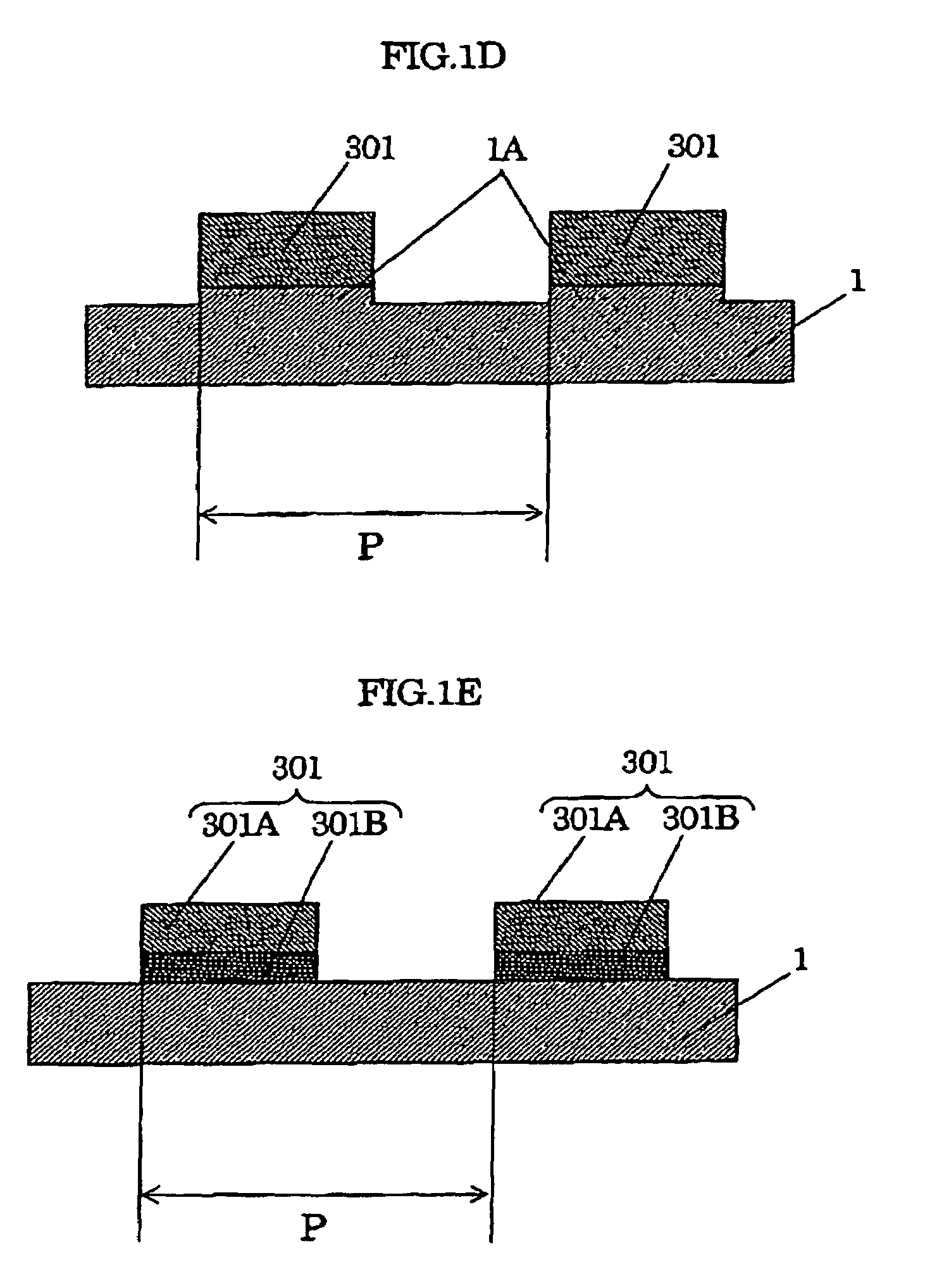
[0106]Samples 3 and 4 employ aluminum (Al) as the material of the electrodes of SAW resonators, and sample 3 has a normalized film thickness h / λ=19.8% while sample 4 uses a thinner film of which h / λ is 15.0%. However, as shown in FIG. 1D, sa...


PUM


Abstract

In a surface acoustic wave (SAW) device, such as a SAW resonator or a SAW filter, loss is minimized and steep characteristics are improved. IDT electrodes and a reflector are provided to a piezoelectric substrate cut out at a cut-angle which allows the substrate to excite a leaky surface acoustic wave (LSAW). The IDT electrodes have a given film thickness and a given pitch “p” of finger-electrodes. A phase velocity of the SAW is reduced to slower than a phase velocity “vb”of a slow shear wave propagating on the piezoelectric substrate, and a resonance frequency “f” satisfies a relation of 2×p≦vb/f. This structure allows the use of a Rayleigh surface acoustic wave (RSAW) which does not produce propagation loss, and improving insertion-loss and steep characteristics from those of a conventional SAW device using the LSAW.

Description

TECHNICAL FIELD[0001]The present invention relates to surface acoustic wave devices having excellent pass-band characteristics, particularly in a high-frequency band, and it also relates to mobile communication apparatuses and sensors both using the same devices.BACKGROUND ART[0002]A surface acoustic wave device (hereinafter referred to as a SAW device) is widely used as a filter or a resonator in radio apparatuses of mobile communication terminals because of its small size and low weight. Since cellular phone systems use higher frequencies, those filters used in the radio apparatuses of mobile communication terminals need to work in the high frequency range between 800 MHz and several GHz, among others. Those filters are required to have low loss in the pass-band, highly attenuate signals in the rejection band, and yet, have steep filter characteristics.[0003]In general, application of a voltage to an inter-digital transducer (IDT), of which finger-electrodes formed on a piezoelect...

Claims


Application Information

Patent Timeline
IPC IPC(8): H03H9/25H03H9/64H03H9/02H03H9/145
CPCH03H9/02661H03H9/6483H03H9/145H03H9/25H03H9/02559H03H9/02929H03H9/64
Inventor TAKAYAMA, RYOICHISEKI, SHUNICHIKAWASAKI, TETSUONAKANISHI, HIDEKAZUHASEGAWA, KOJI
Owner SKYWORKS PANASONIC FILTER SOLUTIONS JAPAN
Why Eureka
Try Eureka