
Chemical-mechanical polishing (CMP) slurry containing clay and CeO2 abrasive particles and method of planarizing surfaces

a technology of ceo2 abrasives and chemical-mechanical polishing, which is applied in the direction of other chemical processes, manufacturing tools, chemistry apparatus and processes, etc., can solve the problems of achieve the effect of improving the glass polishing rate and increasing the polishing ra

Inactive Publication Date: 2006-09-26
AMCOL INTERNATIONAL CORPORATION
View PDF8 Cites 38 Cited by
  • Summary
  • Abstract
  • Description
  • Claims
  • Application Information

AI Technical Summary

Benefits of technology

"The patent describes a polishing composition for glass and semiconductor surfaces that uses a combination of clay and CeO2 particles as abrasive particles. The composition has a synergistic effect, increasing the polishing rate without negatively affecting the finished surfaces. The clay and CeO2 particles have different particle sizes, which change the particle size distribution in the polishing slurry. The composition also includes a chemical accelerator and a complexing or coupling agent to prevent the particles from returning to the surface. The polishing process involves contacting the surface with the abrasive particle-containing composition. The composition can be in the form of a slurry with clay and CeO2 particles dispersed throughout a liquid carrier. The particle size of the CeO2 particles should be in the range of larger than 0.1 μm to 10 μm, with most particles falling within the range of larger than 0.2 μm to 5 μm. The concentration of clay particles in the slurry should be between 0.1% and 10% by weight, and the concentration of CeO2 particles should be between 0.1% and 50% by weight. The composition can be used to planarize glass and insulator surfaces."

Problems solved by technology

In addition, the particle sizes of the clay and CeO2 abrasive particles, in combination, unexpectedly increase the polishing rate, apparently by changing the particle size distribution of the combined abrasive particles in the polishing slurry.

Method used


Image

  • Chemical-mechanical polishing (CMP) slurry containing clay and CeO2 abrasive particles and method of planarizing surfaces
  • Chemical-mechanical polishing (CMP) slurry containing clay and CeO2 abrasive particles and method of planarizing surfaces
  • Chemical-mechanical polishing (CMP) slurry containing clay and CeO2 abrasive particles and method of planarizing surfaces

Examples


example 1

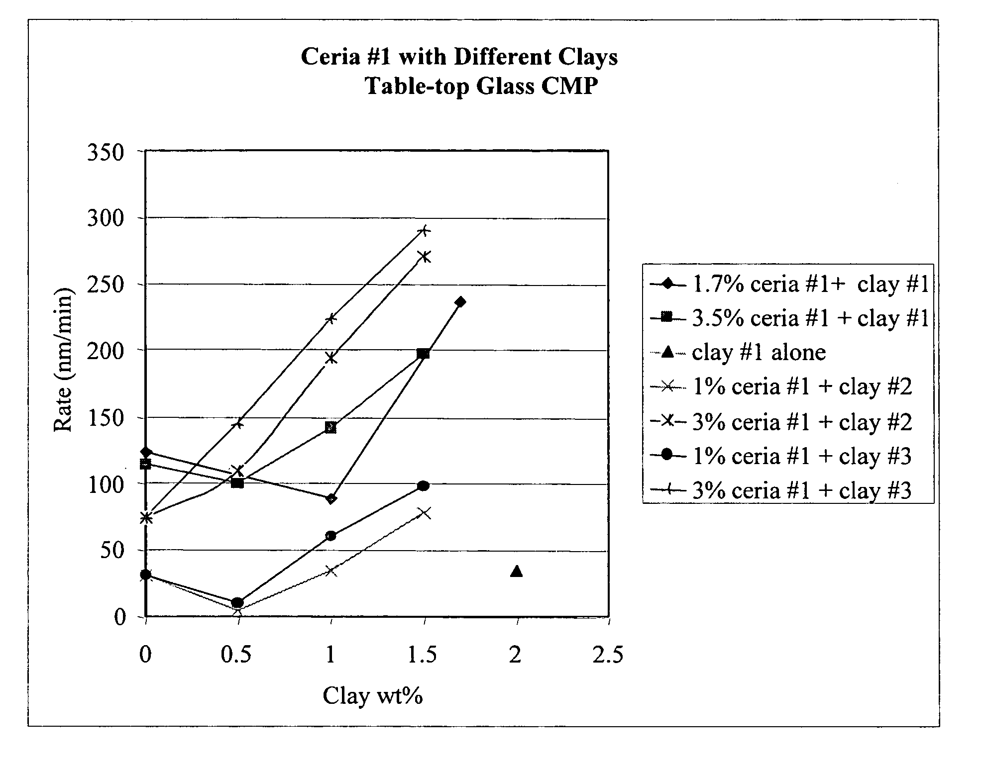
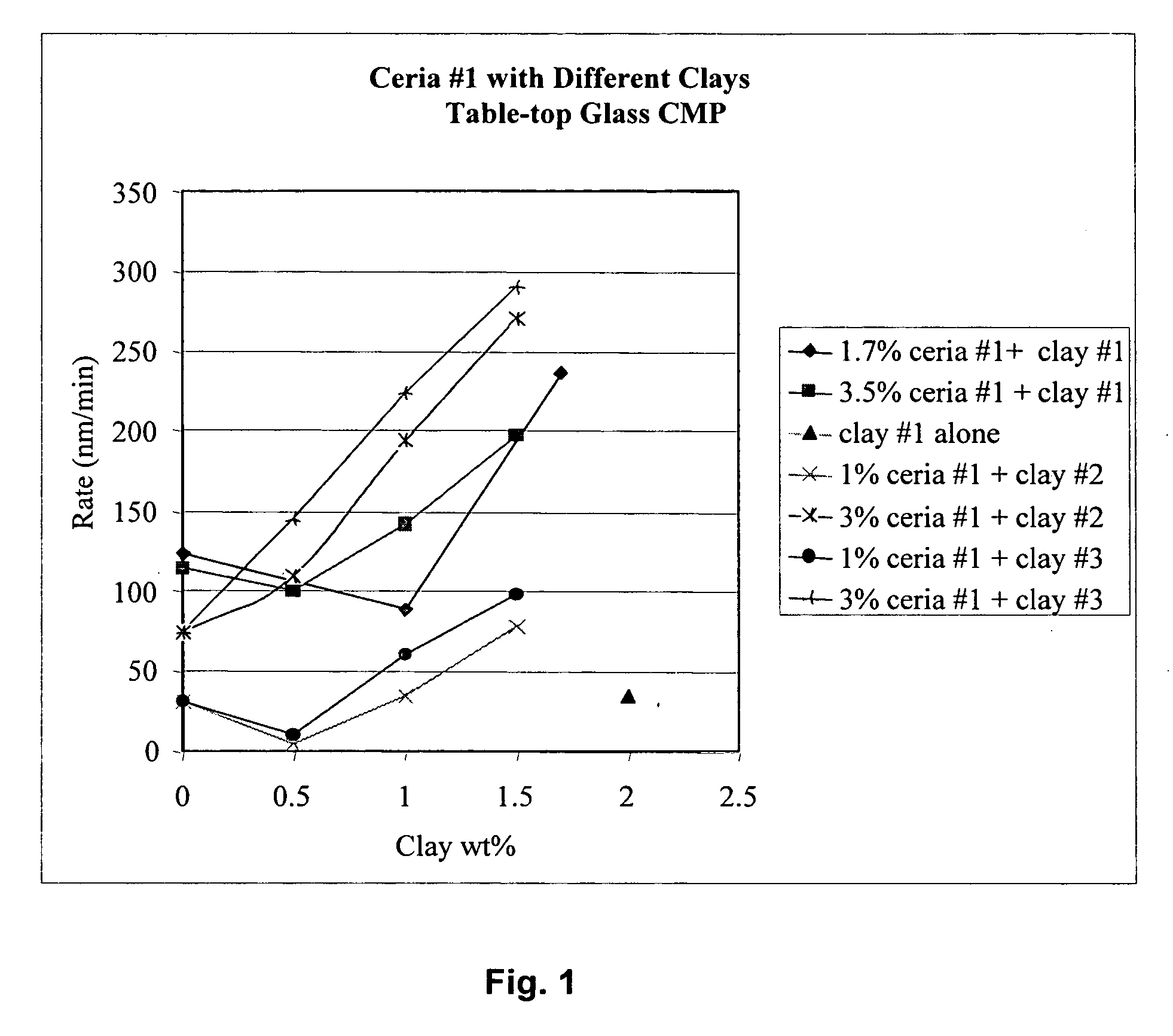
[0046]The polishing experiments were carried out using a bench-top Struers DAP-V polisher. The pure quartz disks (CHEMGLASS, INC., CGQ-0600-03) have a diameter of 1 inch and a thickness of 0.25 inch. The polishing pads were IC-1400 (CR IC 1400-A3, 8 inches in diameter, K-GRV grooved, PSA) provided by Rodel, Inc. The pads were hand-conditioned with 220-grit sandpaper and a nylon brush before being used. The center-to-center distance between the disk and the pad was 5.5 cm. The polishing table and the disk holder are both rotated at a speed of 100 rpm in the same clockwise direction. The applied downward pressure is 5 psi and the slurry flow rate is 30 ml / min. The polishing rates were determined from the mass loss of glass from the disks during 3 minute, 6 minute, 9 minute and 12 minute polishing runs and the reported values are the average of these four runs.

[0047]The following Tables 2–4 and FIGS. 1–3 show the rate of glass removal using the slurry polishing compositions containing ...

example 2

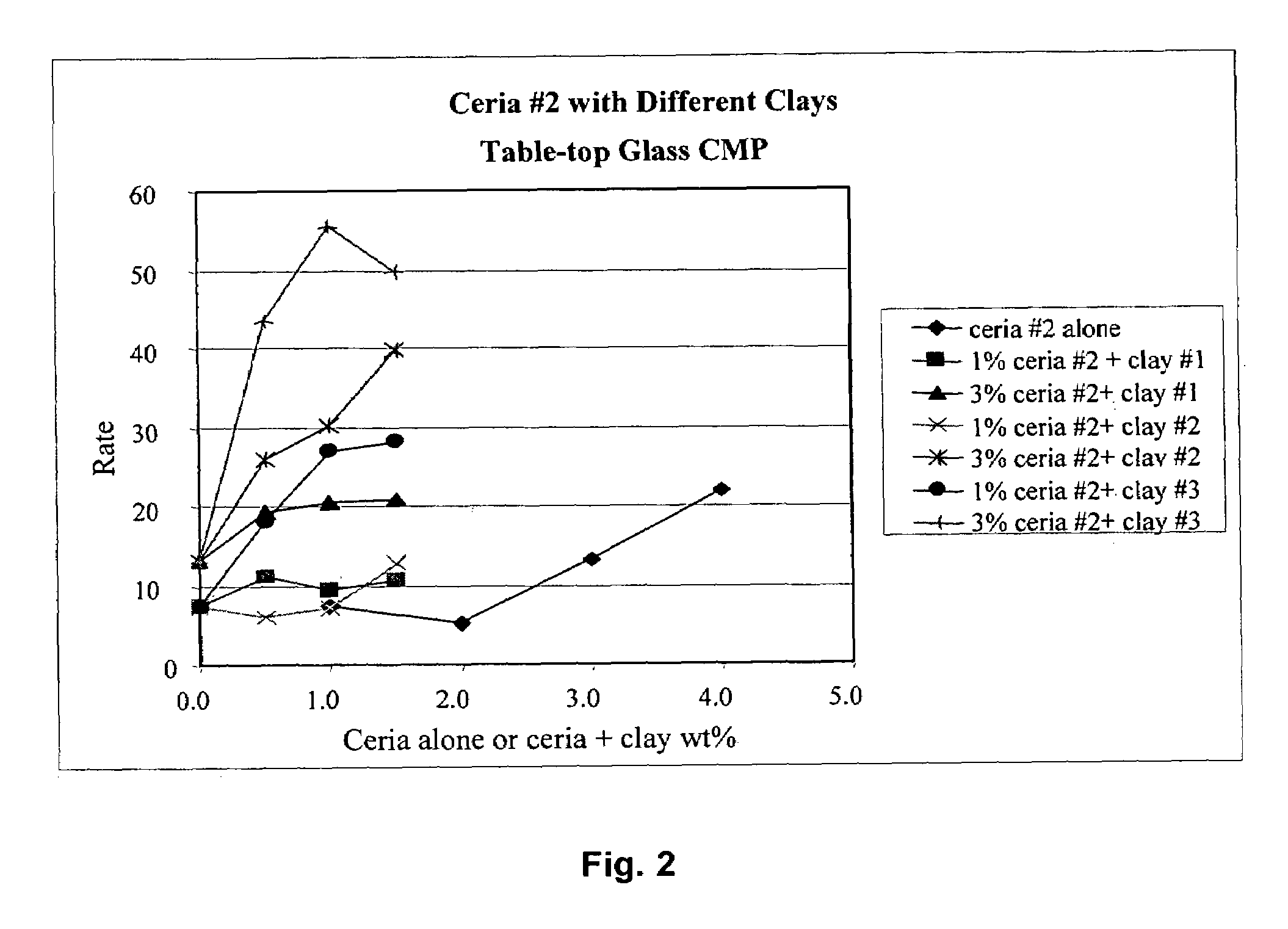
[0050]The same procedure was carried out as in Example 1, using the same three sodium montmorillonite clay abrasive particles, but using CeO2 #2 abrasive particles that were negatively charged, having a mean particle size of 650 nm. The percentages of clay and negatively charged CeO2 abrasive particles were varied, as shown in Table 3, and FIG. 2.

[0051]

TABLE 3Glass CMP results using ceria #2 with different clays at pH = 10.*Ceria #2Clay #1(wt %)(wt %)Clay #2 (wt %)Clay #3 (wt %)Rate (nm / min)1.0742.0513.01314.02191.00741.00.51111.01941.01.51063.001313.00.51943.012053.01.52081.00741.00.5601.01711.01.51283.001313.00.52593.013023.01.53981.00741.00.51821.012701.01.52823.001313.00.54363.015553.01.5498*CeO2 particles are negatively charged at pH = 10

[0052]As shown in Table 3 and FIG. 2, the CeO2 #2 particles alone provide a better polishing rate than the combination of CeO2 and clay until a synergistic combination is reached. The amount of clay necessary in combination with the CeO2 varies...

example 3

[0053]The same procedure was carried out as in Example 1, using the same three sodium montmorillonite clay abrasive particles, but using CeO2 #3 abrasive particles that were positively charged, having a mean particle size of 165 nm. The percentages of clay and positively charged CeO2 abrasive particles were varied, as shown in Table 4, and FIG. 3.

[0054]

TABLE 4Glass CMP results using ceria #3 with different clays at pH = 10.*Ceria #3Clay #1(wt %)(wt %)Clay #2 (wt %)Clay #3 (wt %)Rate (nm / min)1.0152.0303.0344.0451.00151.00.5111.011111.01.51713.00343.00.503.012083.01.53131.00151.00.5461.011711.01.51803.00343.00.51973.012933.01.53491.00151.00.5601.011061.01.51543.00343.00.5883.011413.01.5202*CeO2 particles are negatively charged at pH = 10

[0055]The results clearly indicate that all clay abrasive particles (#1, #2, and #3) have strong synergistic effects with all three different abrasive ceria particles in chemical mechanical polishing (CMP). When synergistic amounts of clay are added, t...


PUM

PropertyMeasurementUnit
particle sizeaaaaaaaaaa

Abstract

A composition for planarizing or polishing a surface comprising (a) a liquid carrier, and (b) solids comprising about 0.1 to about 10% by weight clay abrasive particles, and about 0.1% to about 50% by weight CeO2 particles, based on the total weight of solids in the composition, said clay and CeO2 abrasive particles having a particle size such that at least 90% of the particles (by number), when slurried in water, have a particle size in the range of about 10 nm to about 10 μm.

Description

TECHNICAL FIELD[0001]The present invention is directed to abrasive compositions containing clay and CeO2 abrasive particles and methods of planarizing or polishing surfaces, particularly glass surfaces. The composition is used as an aqueous slurry, and also is useful as a planarization composition in the manufacture of microelectronic devices, e.g., integrated circuits, wafers, memory disks and rigid disks.BACKGROUND[0002]Compositions for planarizing or polishing the surface of a substrate are well known in the art. Polishing slurries typically contain an abrasive material in an aqueous solution and are applied to a surface by contacting the surface with a polishing pad saturated with the slurry composition. Typical abrasive materials include silicon dioxide, cerium oxide, aluminum oxide, zirconium oxide, and tin oxide. U.S. Pat. No. 5,527,423, for example, describes a method for chemically-mechanically polishing a metal layer by contacting the surface with a polishing slurry compri...

Claims


Application Information

Patent Timeline
Patent Type & Authority Patents(United States)
IPC IPC(8): B24B1/00C03C19/00C09G1/02C09K3/14H01L21/00H01L21/3105H01L21/321
CPCC03C19/00C09G1/02H01L21/3212C09K3/1463H01L21/31053C09K3/1409
Inventor FANG, MINGMINGIANIRO, MICHAEL R.EISENHOUR, DON
Owner AMCOL INTERNATIONAL CORPORATION
Learn More