Devices and methods for heart valve treatment

a heart valve and treatment device technology, applied in the field of heart valve treatment devices and methods, can solve the problems of valve insufficiency, poor coaptation of valve leaflets, and inability to fully coapt the leaflets, so as to improve the function of the valve and increase the coaptation of the leaflets

Active Publication Date: 2006-09-26
EDWARDS LIFESCIENCES LLC
View PDF663 Cites 242 Cited by
  • Summary
  • Abstract
  • Description
  • Claims
  • Application Information

AI Technical Summary

Benefits of technology

[0012]To address these needs, the present invention provides, in exemplary non-limiting embodiments, devices and methods for improving the function of a valve (e.g., mitral valve) by positioning a spacing filling device outside and adjacent the heart wall such that the device applies an inward force against the heart wall acting on the valve. The device may be remotely secured to the heart wall. The securement may provide a substantially equal and opposite force to the inward force, or a substantially equal and opposite outward force may be applied against anatomical structure outside the heart wall. The inward force is sufficient to change the function of the valve, and may increase coaptation of the leaflets, for example. The spacing filling device may be implanted outside the epicardium, such as between the epicardium and the pericardium, and may be attached to epicardium while remaining free of the pericardium.

Problems solved by technology

Various etiologies may result in heart valve insufficiency depending upon both the particular valve as well as the underlying disease state of the patient.
For instance, a congenital defect may be present resulting in poor coaptation of the valve leaflets, such as in the case of a monocusp aortic valve, for example.
Valve insufficiency also may result from an infection, such as rheumatic fever, for example, which may cause a degradation of the valve leaflets.
In such cases, the valve components may be normal pathologically, yet may be unable to function properly due to changes in the surrounding environment.
In any case, the resultant volume overload that exists as a result of an insufficient valve may increase chamber wall stress.
Such an increase in stress may eventually result in a dilatory process that further exacerbates valve dysfunction and degrades cardiac efficiency.
These disease states often lead to dilatation of the left ventricle.
Such dilatation may cause papillary muscle displacement and / or dilatation of the valve annulus.
Moreover, as the annulus dilates in response to chamber enlargement and increased wall stress, increases in annular area and changes in annular shape may increase the degree of valve insufficiency.
Annular dilatation also may result in a flattening of the valve annulus from its normal saddle shape.
Alterations in functional capacity also may cause valve insufficiency.
Reductions in annular contractility commonly observed in ischemic or idiopathic cardiomyopathy patients therefore hamper the closure of the valve.
However, under higher loading resulting from an increase in output requirement, the valve may become incompetent.
In many of these cases, the importance of preserving the native subvalvular apparatus was not fully appreciated and many patients often acquired ventricular dysfunction or failure following the surgery.
Though later experience was more successful, significant limitations to valve replacement still exist.
In the case of biologically derived devices, in particular those used as mitral valve replacements, the long-term durability may be limited.
Thus, the use of such devices in younger patient groups is impractical.
Such rings, however, generally flatten the natural saddle shape of the valve and hinder the natural contractility of the valve annulus.
A limitation of each of these techniques is that they typically require opening the heart to gain direct access to the valve and the valve annulus.
This generally necessitates the use of cardiopulmonary bypass, which may introduce additional morbidity and mortality to the surgical procedures.
Additionally, for each of these procedures, it is very difficult to evaluate the efficacy of the repair prior to the conclusion of the operation.

Method used


Image

  • Devices and methods for heart valve treatment
  • Devices and methods for heart valve treatment
  • Devices and methods for heart valve treatment

Examples


Embodiment Construction

[0025]The following detailed description should be read with reference to the drawings in which similar elements in different drawings are numbered the same. The drawings, which are not necessarily to scale, depict illustrative embodiments and are not intended to limit the scope of the invention.

[0026]General Description of Space Filling Device Function and Use

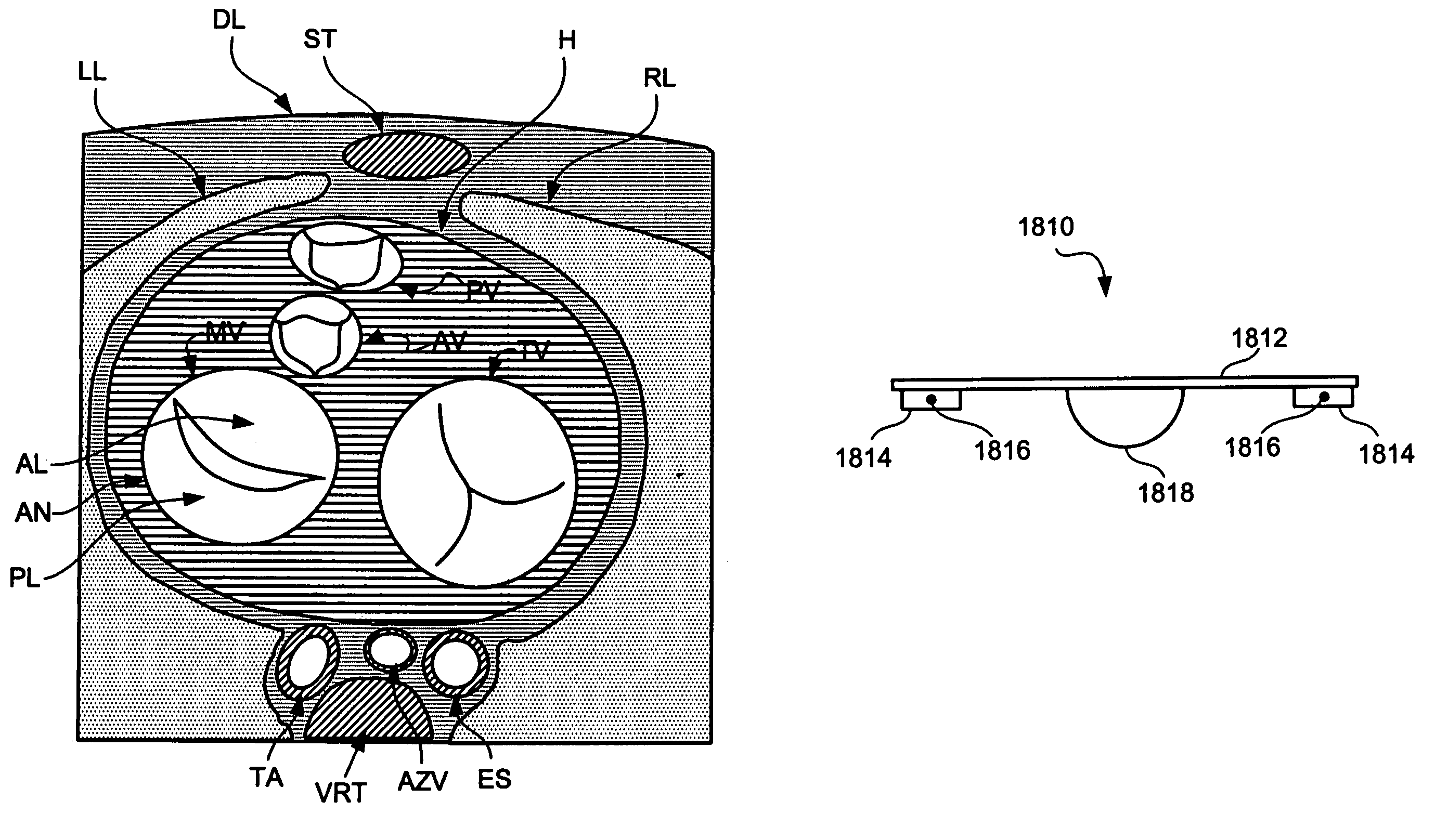
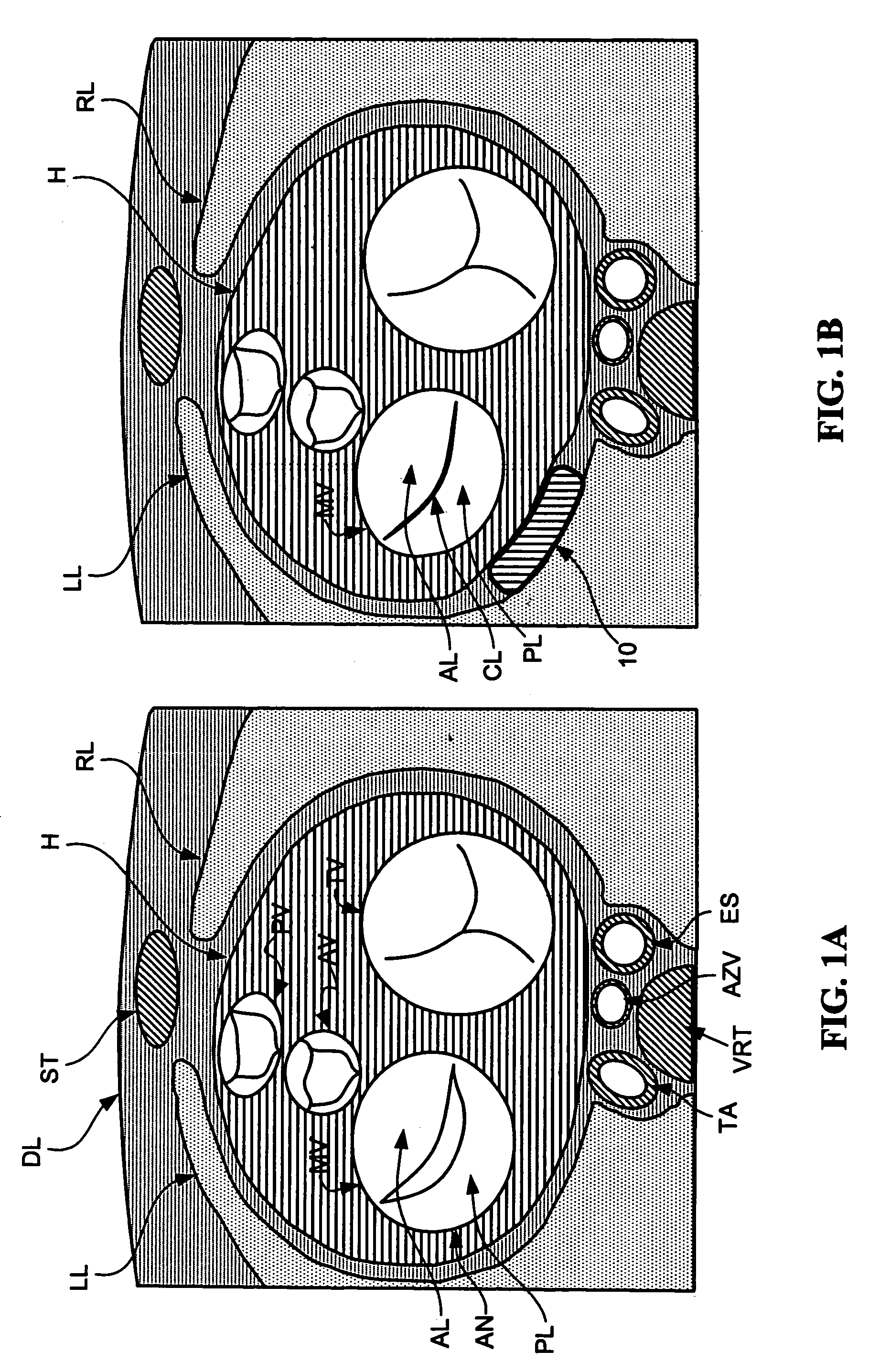
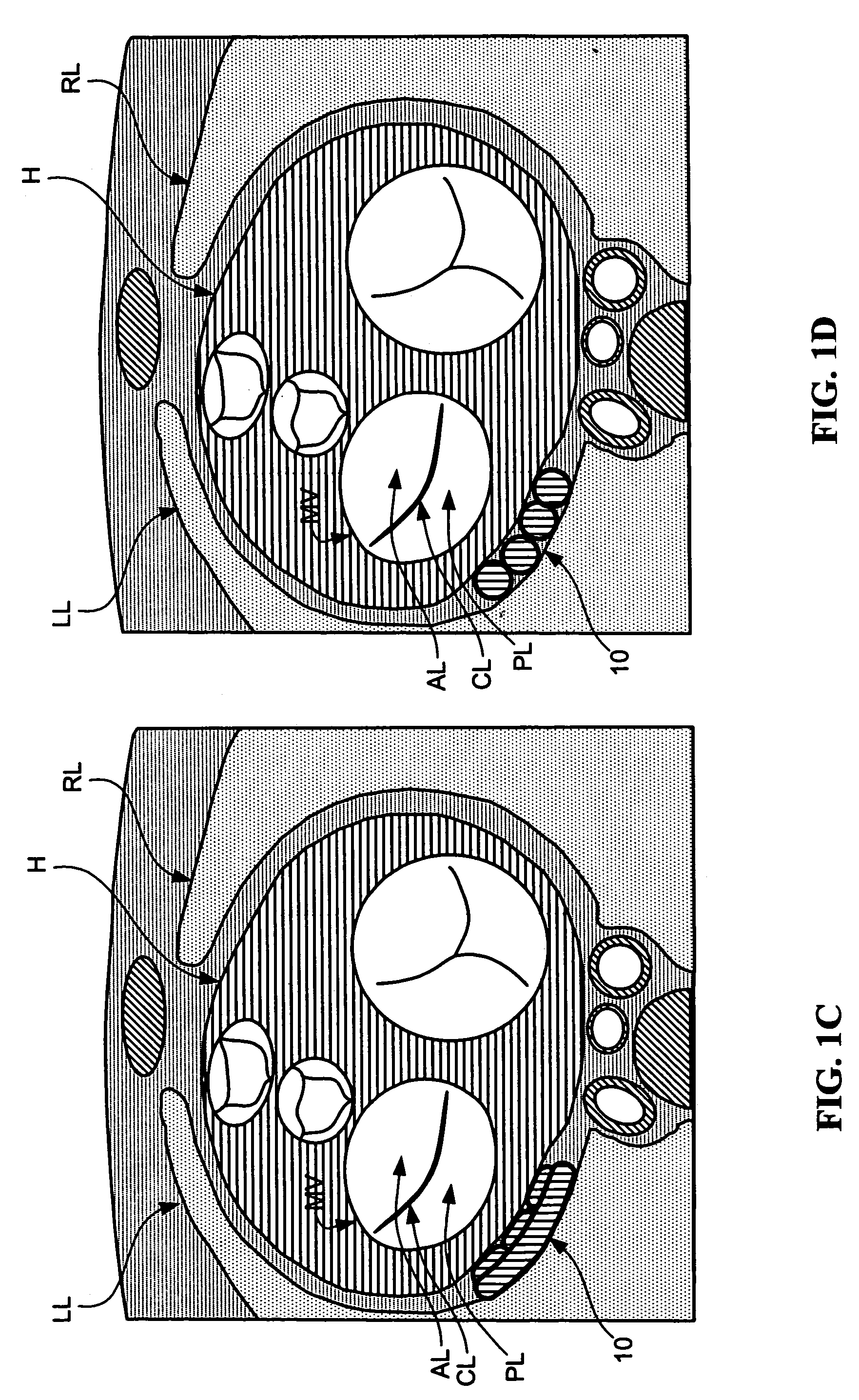
[0027]The various aspects of the devices and methods described herein generally pertain to devices and methods for treating heart conditions, including, for example, dilatation, valve incompetencies, including mitral valve leakage, and other similar heart failure conditions. Each disclosed device may operate passively in that, once placed in the heart, it does not require an active stimulus, either mechanical, electrical, hydraulic, pneumatic, or otherwise, to function. Implanting one or more of the devices operates to assist in the apposition of heart valve leaflets to improve valve function.

[0028]In addition, these devices m...


PUM


Abstract

Devices and methods for improving the function of a valve (e.g., mitral valve) by positioning a spacing filling device outside and adjacent the heart wall such that the device applies an inward force against the heart wall acting on the valve. A substantially equal and opposite force may be provided by securing the device to the heart wall, and / or a substantially equal and opposite outward force may be applied against anatomical structure outside the heart wall. The inward force is sufficient to change the function of the valve, and may increase coaptation of the leaflets, for example. The space filling device may be implanted by a surgical approach, a transthoracic approach, or a transluminal approach, for example. The space filling portion may be delivered utilizing a delivery catheter navigated via the selected approach, and the space filling portion may be expandable between a smaller delivery configuration and a larger deployed configuration.

Description

CROSS-REFERENCE TO RELATED APPLICATIONS[0001]This application claims the benefits of priority of U.S. Provisional Application No. 60 / 425,519, filed Nov. 12, 2002, the entire contents of which are incorporated by reference herein.FIELD OF THE INVENTION[0002]The present invention relates to devices and associated methods for treating and improving the performance of dysfunctional heart valves. More particularly, the invention relates to devices and methods that passively assist to reshape a dysfunctional heart valve to improve its performance.BACKGROUND OF THE INVENTION[0003]Various etiologies may result in heart valve insufficiency depending upon both the particular valve as well as the underlying disease state of the patient. For instance, a congenital defect may be present resulting in poor coaptation of the valve leaflets, such as in the case of a monocusp aortic valve, for example. Valve insufficiency also may result from an infection, such as rheumatic fever, for example, which ...

Claims


Application Information

Patent Timeline
Patent Type & Authority Patents(United States)
IPC IPC(8): A61F2/24A61B17/00A61B17/04A61B17/132A61B17/32A61F2/00
CPCA61B17/00234A61B17/04A61F2/2481A61B17/1325A61B17/32053A61B2017/00243A61B2017/0412A61B2017/0464A61B2017/0496A61F2/2442A61B2017/0404Y10S623/904
Inventor VIDLUND, ROBERT M.SCHWEICH, JR., CYRIL J.MORTIER, TODD J.SCHROEDER, RICHARDEKVALL, CRAIGKALGREEN, JASONMATTHEES, EDWARDKUSZ, DAVID
Owner EDWARDS LIFESCIENCES LLC
Why Eureka
Try Eureka