Technique and electronic circuitry for quantifying a transient signal using threshold-crossing counting to track signal amplitude

a technology of transient signal and counting, applied in the direction of noise figure or signal-to-noise ratio measurement, instruments, specific gravity measurement, etc., can solve the problem of severe limitation of the practical application of resonator-type sensor units in real-world operation

Inactive Publication Date: 2006-09-26
SEN TECH BIOMED CORP A BUSINESS ENTITY ORGANIZED UNDER LAWS OF COMMONWEALTH OF PENNSYLVANIA
View PDF6 Cites 21 Cited by
  • Summary
  • Abstract
  • Description
  • Claims
  • Application Information

AI Technical Summary

Benefits of technology

[0033]Certain of the several unique features, and unique combinations of features, as supported and contemplated in the instant technical disclosure may provide one or more of a variety of advantages; among these are:
[0037](d) Manufacturability—The unique circuitry can be built using conventional or modified micro-components / devices employing known integrated circuit (IC) fabrication techniques for reproduction on a wide scale, allowing for assembly-line type production in an economically feasible manner.

Problems solved by technology

The use of either a lock-in amplifier or FFT analysis imposes a severe limitation to practical application of resonator-type sensor units in real-world operation.

Method used


Image

  • Technique and electronic circuitry for quantifying a transient signal using threshold-crossing counting to track signal amplitude
  • Technique and electronic circuitry for quantifying a transient signal using threshold-crossing counting to track signal amplitude
  • Technique and electronic circuitry for quantifying a transient signal using threshold-crossing counting to track signal amplitude

Examples


examples of embodiments

OF THE INVENTION

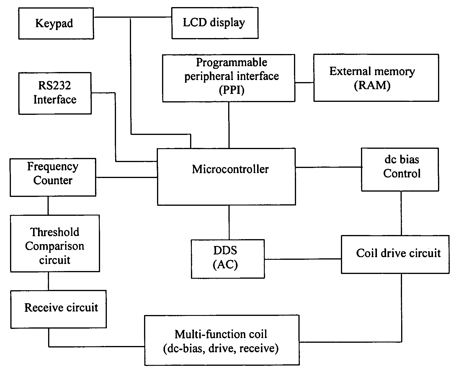
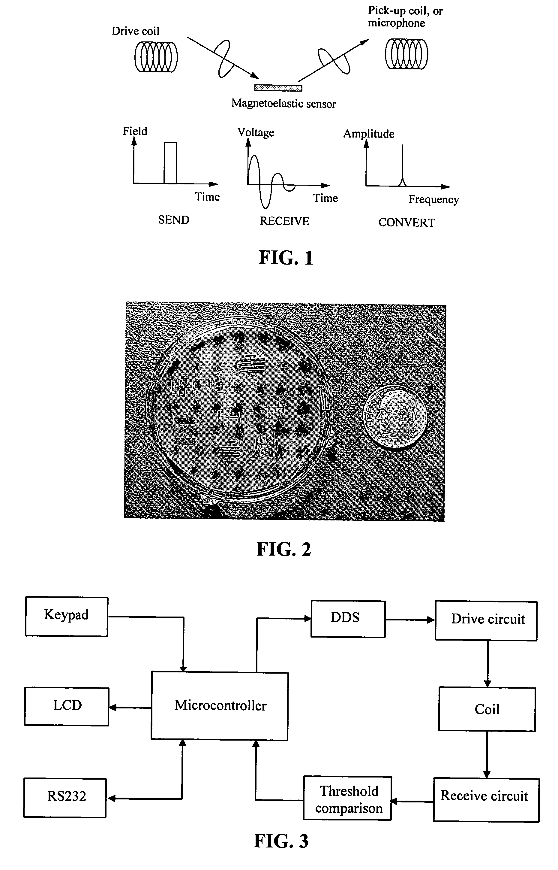
[0117]By way of example only, two sensing systems are described, next. Example System 1 employs a high-speed DS87C520 microcontroller that can directly perform the frequency counting operation (no need for external counter units). Example System 2 uses a lower-cost AT89S53 microcontroller, an external counter(s) to precisely count the time for the frequency counting operation, and features software-controlled dc biasing field and thresholds. Along with a microcontroller (such as that depicted in FIGS. 3, 4), the following are employed: a threshold comparison circuit (e.g., FIGS. 7, 11) for signal conversion, an interrogation circuit that consists of a drive amplifier (e.g., FIG. 9), an instrumentation amplifier (e.g., FIG. 10), and a multifunctional interrogation coil (e.g., FIG. 8). The circuitry can be packaged into a compact plastic container, or other suitable material, along with a receiver-element such as a solenoid coil. For sensor interrogation, a ‘ring-and-l...

example 1

[0118]The microcontroller used in the design is a DS87C520 from Dallas Semiconductor Corporation. The DS87C520 microcontroller belongs to the 8051 family having the following characteristics: speed is up to 33 MHz crystal frequency, on-chip memory is 16 KB of ROM and 1 KB of MOVX RAM, has three internal 16-bit timers (labeled Timer 0–2) that are used in combination (FIGS. 7, 11, 14) to electronically implement the threshold-crossing counting technique for frequency measurement, damping measurement, and amplitude-frequency spectrum analysis according to the invention.

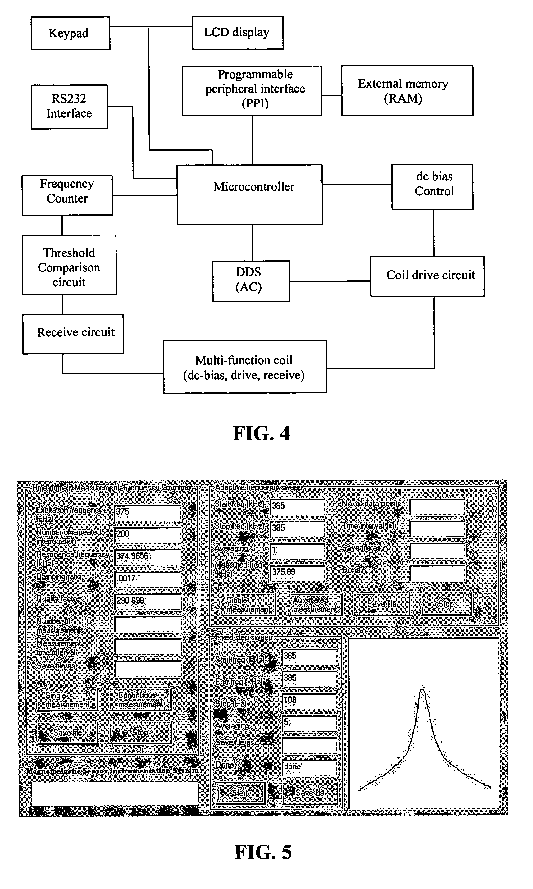
[0119]Direct digital synthesis (DDS) is a technique that is used to generate a frequency-agile, highly pure sine wave, or any arbitrary waveforms, from an accurate reference clock. The frequency of the output is digitally controlled by an N-bit digital word that allows sub-Hz frequency agility. The output waveform is normally reconstructed with a high-speed digital to analog converter (DAC). The magnetoelastic sensor sys...

example 2

[0123]Core functionalities for the Example System 2 are the same as for Example System 1, plus the dc biasing field and the threshold voltages in the comparator circuit can be adjusted via software. This permits the system to monitor sensor elements of different sizes and shapes, where different biasing fields and thresholds are used, without requiring the change-out of circuitry components. Example System 2 uses a lower-cost microcontroller than that of Example System 1. The microcontroller unit AT89S53 distributed by Atmel of Example System 2 has similar features and performance, to that of the DS87C520, but the timer / counters speed is slower. If microcontroller speed is insufficient to perform certain of the counting / timing function(s), counter(s) that are external to the microcontroller are used. To perform a frequency counting operation, the timer / counters of the microcontroller have to track the number of cycles of the sensor transient signal, as well as the elapsed time durin...


PUM

PropertyMeasurementUnit
threshold voltageaaaaaaaaaa
resonance frequencyaaaaaaaaaa
lengthaaaaaaaaaa

Abstract

Circuitry adapted for carrying out associated techniques for: (a) calculating a damping factor, e.g., a damping ratio represented by ζ, or a quality factor Q, where ζ≈1 / 2Q, for a transient signal received, having been emitted from a resonator-type sensor element; (b) determining amplitude, A, of the transient signal; or (c) generating a frequency response dataset of interrelated points for the transient signal. A threshold comparison circuit is included for converting the transient signal received into a first and second digital waveform; the first digital waveform represents cycle crossings of the transient signal associated with a first threshold value, and the second digital waveform represents cycle crossings of the transient signal associated with a second threshold value. The transient signal may be converted, likewise, into third, and so on, digital waveforms, whereby the third digital waveform represents cycle crossings of the transient signal associated with a third threshold value. Respective digital counters are included, each of which is adapted for determining a total number of cycles of the first, second, third, and so on, digital waveform. A processing unit of suitable speed and capacity is employed for the calculating of the damping factor, determining an amplitude, and / or generating a frequency response dataset.

Description

BACKGROUND OF THE INVENTIONField of the Invention[0001]In general, the present invention relates to techniques for characterizing emissions from resonator-type sensor elements such as magnetoelastic resonant sensor elements, quartz crystal microbalance (QCM) elements, piezoelectric acoustic wave elements, etc.—to gain useful information from the sensor elements about an environment, analyte or sample of interest. These resonator-type elements each vibrate in response to sine wave excitation and impulse excitation. More-particularly, the invention is directed to unique circuitry adapted for carrying out associated unique techniques for: (a) calculating a damping factor, e.g., a damping ratio represented by ζ, or a quality factor Q which is related to a damping ratio, ζ≈1 / 2Q, for a transient signal received, having been emitted from a resonator-type sensor element; (b) determining amplitude, A, of the transient signal; or (c) generating a frequency response dataset of interrelated poi...

Claims


Application Information

Patent Timeline
Patent Type & Authority Patents(United States)
IPC IPC(8): G01R13/00G01N11/00
CPCG01N29/032G01N29/11G01N29/2412G01N29/4427G01N29/46G01N9/002G01N2291/0427G01N2291/014G01N2291/02818G01N2291/0422G01N2291/0426
Inventor ZENG, KEFENGONG, KEAT G.GRIMES, CRAIG A.
Owner SEN TECH BIOMED CORP A BUSINESS ENTITY ORGANIZED UNDER LAWS OF COMMONWEALTH OF PENNSYLVANIA
Why Eureka
Try Eureka