CT imaging system with multiple peak x-ray source

a computed tomography and imaging system technology, applied in tomography, instruments, nuclear engineering, etc., can solve the problems of inability to determine whether there is a calcium build-up in the blood vessels of patients, poor spatial and low contrast resolution between each combination, and inability to achieve the effect of reducing x-ray exposure to patients, improving spatial and low contrast resolution, and increasing ease of differentiation

Active Publication Date: 2006-10-10
GE MEDICAL SYST GLOBAL TECH CO LLC
View PDF29 Cites 62 Cited by
  • Summary
  • Abstract
  • Description
  • Claims
  • Application Information

AI Technical Summary

Benefits of technology

[0013]Another advantage of the present invention is that it provides improved spatial and low contrast resolution between different materials, thus further providing increased ease in differentiating between scanned materials.
[0014]Furthermore, the present invention provides energy discrimination while minimizing x-ray exposure to a patient.
[0015]The present invention itself, together with attendant advantages, will be best understood by reference to the following detailed description, taken in conjunction with the accompanying figures.

Problems solved by technology

Combination of Iodide and water or blood, which consists mainly of water, and a combination of calcium deposits and soft tissue exhibit similar material densities, resulting in poor spatial and low contrast resolution between each combination and having effectively similar corresponding brightness levels when viewed by a practitioner.
It is undesirable to have calcium build-up on inner linings of blood vessel walls.
Thus, the practitioner, due to difficulty in discerning between the brightness levels of reconstructed CT images for the stated combinations, may not be able to determine whether there exists a calcium build-up in the blood vessels of the patient.
As is known in the art, it is difficult from the resulting energy spectrum and from inherent characteristics of integration to differentiate between similar material densities.

Method used


Image

  • CT imaging system with multiple peak x-ray source
  • CT imaging system with multiple peak x-ray source
  • CT imaging system with multiple peak x-ray source

Examples


Embodiment Construction

[0025]In each of the following figures, the same reference numerals are used to refer to the same components. While the present invention is described with respect to system and method of performing energy discrimination within a computed tomography (CT) imaging system, the following apparatus and method is capable of being adapted for various purposes and is not limited to the following applications: MRI systems, CT systems, radiotherapy systems, X-ray imaging systems, ultrasound systems, nuclear imaging systems, magnetic resonance spectroscopy systems, and other applications known in the art.

[0026]In the following description, various operating parameters and components are described for one constructed embodiment. These specific parameters and components are included as examples and are not meant to be limiting.

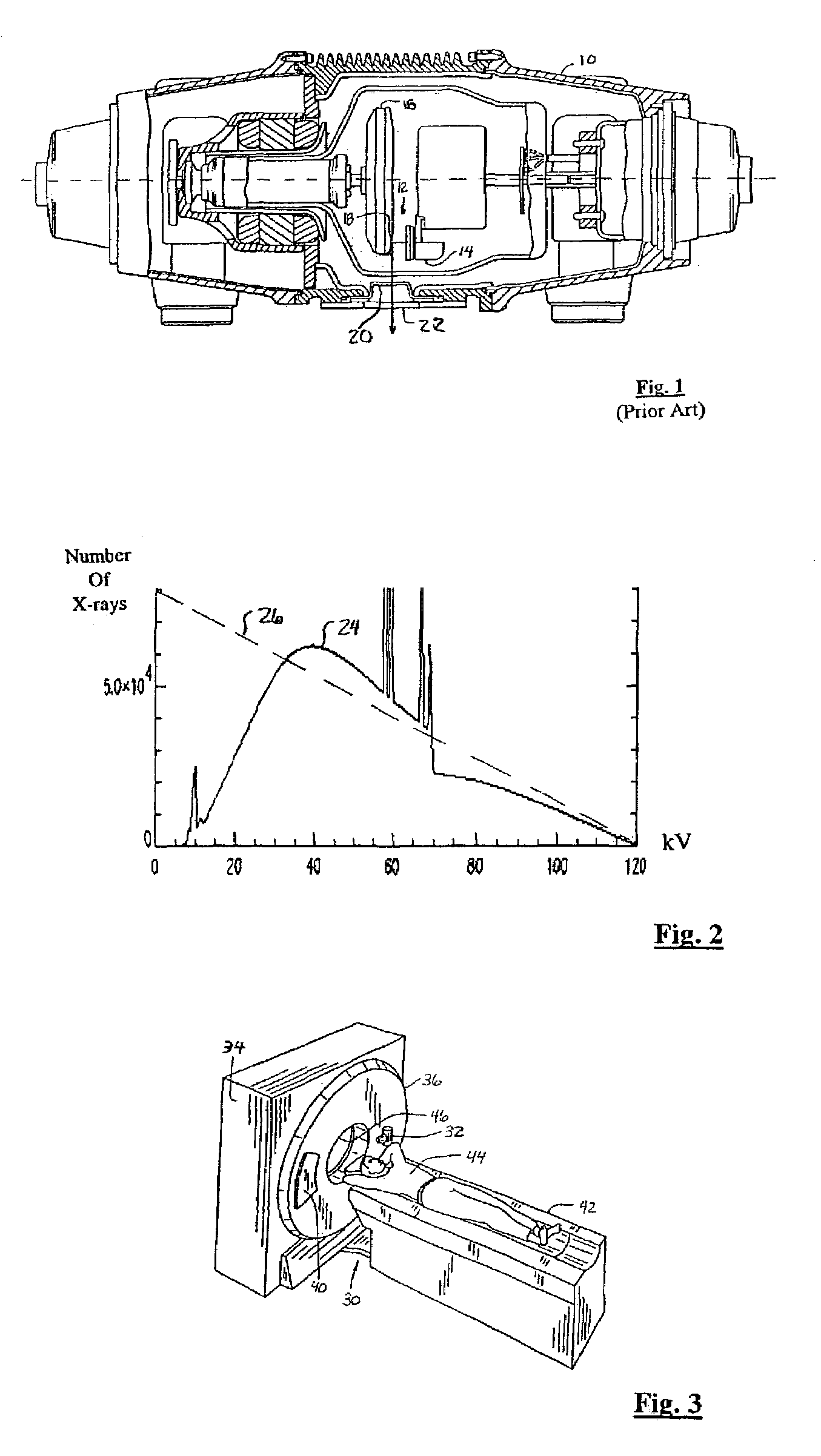
[0027]Also, in the following description the term “x-ray quantity energy peaks” refers to general shape of an energy spectrum plot and peaks contained therein. An energy s...


PUM


Abstract

An x-ray source (32) for performing energy discrimination within an imaging system (10) includes a cathode-emitting device (82) emitting electrons and an anode (81) that has a target (80) whereupon the electrons impinge to generate an x-ray beam (93) with multiple x-ray quantity energy peaks (116 and 120). A method of performing energy discrimination in the imaging system (10) includes emitting the electrons. The x-ray beam (93) with the x-ray quantity energy peaks (116 and 120) is generated. The x-ray beam (93) is directed through an object (44) and is received. An x-ray image having multiple energy differentiable characteristics is generated in response to the x-ray beam (93).

Description

CROSS REFERENCE TO RELATED APPLICATIONS[0001]The present invention is related to U.S. patent application Ser. No. 10 / 064,775, filed on Aug. 15, 2002, now U.S. Pat. No. 6,819,738, and entitled “A Hybrid Scintillator / Photo Sensor and Direct Conversion Detector”, which is incorporated by reference herein.BACKGROUND OF INVENTION[0002]The present invention relates generally to multi-slice computed tomography (CT) imaging systems, and more particularly, to a system and method of performing energy discrimination therein.[0003]In computed topography (CT) imaging portions of a patient are scanned and density of materials contained therein are determined for various diagnostic and evaluation purposes. There is a continuous effort to increase CT imaging system scanning capabilities. Specifically, in CT imaging it is desirable not only to be capable of determining density of scanned materials, but also to be able to distinguish between materials or combinations of materials that have similar de...

Claims


Application Information

Patent Timeline
Patent Type & Authority Patents(United States)
IPC IPC(8): H05G1/02G21K3/00H01J35/06A61B6/03G01T1/20G01T1/24G21K5/02H01J35/10H05G1/46H05H1/00
CPCA61B6/032A61B6/4035A61B6/4241A61B6/482H01J35/06A61B6/4007A61B6/4021H01J2235/068A61B6/027H01J35/064
Inventor HOFFMAN, DAVID M.
Owner GE MEDICAL SYST GLOBAL TECH CO LLC
Why Eureka
Try Eureka