Control strategy for flexible catalytic combustion system

a flexible catalytic combustion and control strategy technology, applied in the direction of combustion type, combustion of catalytic materials, turbine/propulsion engine ignition, etc., can solve the problems of catalyst overheating, catalyst loss activity in a very short time, system may have a much more limited window of operation, etc., to achieve sufficient control system calculation speed and good process control

Inactive Publication Date: 2006-10-17
KAWASAKI HEAVY IND LTD
View PDF79 Cites 40 Cited by
  • Summary
  • Abstract
  • Description
  • Claims
  • Application Information

AI Technical Summary

Benefits of technology

[0019]It is to be understood that system control in accordance with the present invention comprises operating the system at, or near, conditions defined by an operating line data set wherein a first variable (e.g. the fuel air ratio value at the catalyst inlet) is used to specify a second variable (e.g. the catalyst inlet gas temperature) with the control system acting to control this second variable to the specified value by adjusting fuel flow to the flame burner. An advantage of the present system is that it can be used to control the operation of a gas turbine / catalytic combustion system, allowing the gas turbine to start up and operate over a wide load range with very low emissions.
[0040]In accordance with the present invention, one or more sensors may be used to periodically (or continuously) re-determine the location of the homogeneous combustion process wave, such that system operation may be controlled to move the homogeneous combustion process wave to a preferred location. As such, the present system periodically (or continuously) tracks changes of a catalyst operation specification and then shifts system operation by “updating” to a new operating line (ie: selecting a new operating schedule from among a family of predetermined schedules). Accordingly, the operating line (i.e.: the preferred relationship between the fuel air ratio and the temperature at the catalyst inlet at which minimal emissions occur) can be periodically (or continuously) updated to achieve reduced (or preferably, minimal) emissions as the catalyst changes performance with time.
[0044]In accordance with the present invention, the predetermined schedule (or schedules) relating the fuel air ratio and the catalyst inlet gas temperature may be based on schedules, lookup tables or mathematical functions stored in the memory of a computerized control system which controls the system operation using this information. Optionally, additional information can be input into the computerized control system such as temperatures, fuel or air flow rates, load and other values. In preferred aspects, the calculation speed of the control system is sufficiently fast such that the control system can react very quickly to changes in the process and can thus provide very good control of the process.

Problems solved by technology

Unfortunately, however, such systems may have a much more limited window of operation compared to conventional diffusion flame or lean premix combustors.
For example, fuel / air ratios above a certain limit may cause the catalyst to overheat and lose activity in a very short time.

Method used


Image

  • Control strategy for flexible catalytic combustion system
  • Control strategy for flexible catalytic combustion system
  • Control strategy for flexible catalytic combustion system

Examples


Embodiment Construction

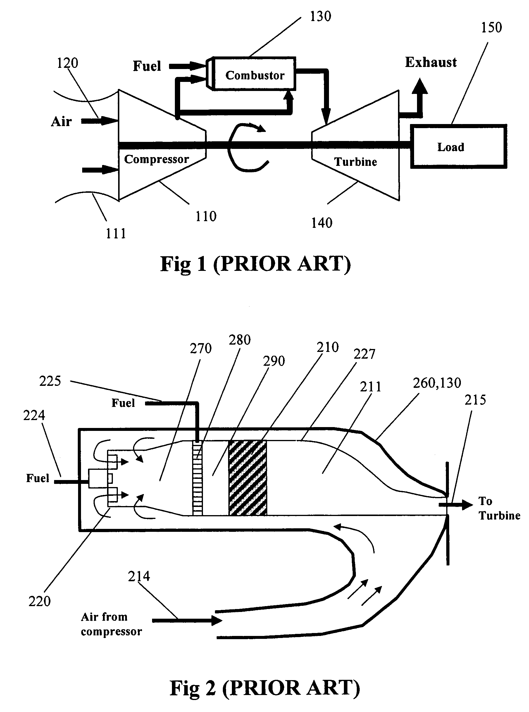
[0058]FIG. 1 schematically shows an example of a typical existing gas turbine employing a catalytic combustion system. In this system, compressor 110 ingests ambient air 120 through compressor bellmouth 111, and compresses this air to a high pressure and then drives the compressed air, at least in part, through the combustor 130 and then through the drive turbine 140. Combustor 130 combines fuel and the air and combusts this mixture to form a hot high velocity gas stream that flows through the turbine 140 which provides the power to drive the compressor and the load 150 such as a generator.

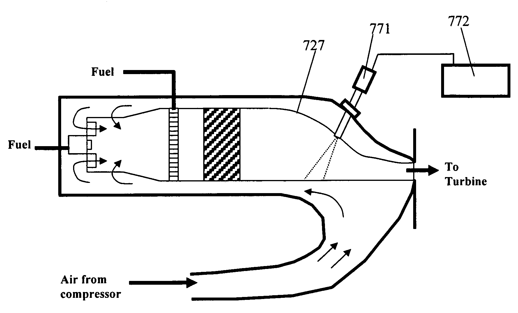
[0059]FIG. 2 is a close-up view of combustor 130 of FIG. 1. Specifically, as shown in FIG. 2, a catalytic combustor 260 is provided. Catalytic combustor 260 comprises four major elements that are arrayed serially in the flow path. Specifically, these four elements include a flame burner 220 (which is positioned upstream of the catalyst and which produces a hot gas mixture 270), a fuel injection an...


PUM


Abstract

A control system for a catalytic combustion system on a gas turbine includes a flame preburner, a fuel injector positioned downstream of the preburner and a catalyst positioned downstream of the fuel injector. In such systems, a portion of the fuel combusts within the catalyst itself and the remainder of the fuel combusts in a homogeneous combustion process wave downstream of the catalyst. A sensor in communication with the control system monitors the homogeneous combustion process wave and adjusts the gas temperature at the catalyst inlet to a preferred value based on a predetermined schedule that relates the catalyst inlet gas temperature to operating fundamentals such as adiabatic combustion temperature or the gas turbine's exhaust gas temperature.

Description

RELATED APPLICATION[0001]This application is a regular application of, and claims the benefit of priority from U.S. Provisional Patent Application No. 60 / 262,282 filed Jan. 16, 2001, the full disclosure of which is incorporated herein by reference.BACKGROUND OF THE INVENTION[0002]In a conventional gas turbine engine, the engine is controlled by monitoring the speed of the engine and adding a proper amount of fuel to control the engine speed. Specifically, should the engine speed decrease, fuel flow is increased thus causing the engine speed to increase. Similarly, should the engine speed increase, fuel flow is decreased causing the engine speed to decrease. In this case, the engine speed is the control variable or process variable monitored for control.[0003]A similar engine control strategy is used when the gas turbine is connected to an AC electrical grid in which the engine speed is held constant as a result of the coupling of the generator to the grid frequency. In such a case, ...

Claims


Application Information

Patent Timeline
Patent Type & Authority Patents(United States)
IPC IPC(8): F02C7/22F02C7/26F02C7/08F02C9/00F02C9/28F23C13/00F23C99/00F23L15/04F23N5/00F23N5/08F23N5/12F23R3/40
CPCF23C13/00F23L15/04F23R3/40F23C2900/13002F23D2208/10Y02E20/34
Inventor YEE, DAVID K.VELASCO, MARCO A.NICKOLAS, SARENTO G.DALLA BETTA, RALPH A.
Owner KAWASAKI HEAVY IND LTD
Why Eureka
Try Eureka