
System, device and method for limiting tunnel traffic in an information communication network

a technology of information communication network and tunnel traffic, applied in data switching network, frequency-division multiplex, instruments, etc., can solve problems such as traffic volume limitation, and achieve the effect of avoiding destabilization and enhancing the overall speed and efficiency of communication in the network

Active Publication Date: 2006-10-17
AVAYA INC
View PDF6 Cites 42 Cited by
  • Summary
  • Abstract
  • Description
  • Claims
  • Application Information

AI Technical Summary

Benefits of technology

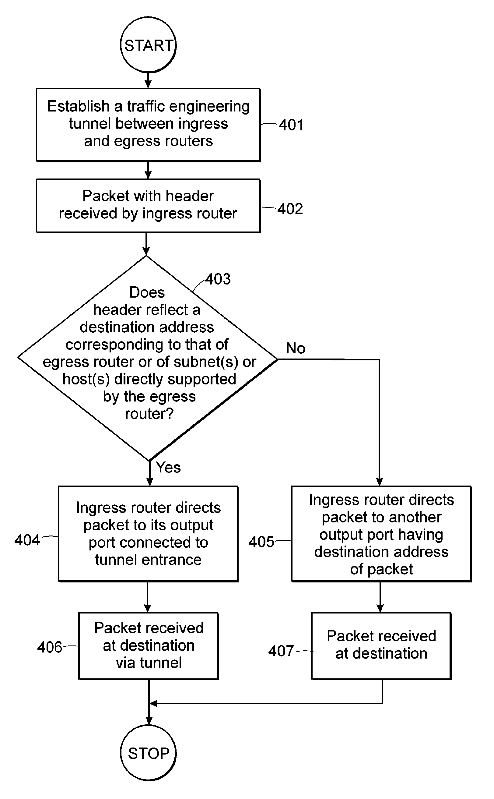
[0008]In another aspect of the present invention the tunnel is a traffic engineered MPLS tunnel and routing of that certain information includes affixing a label to that certain information identifying the tail-end router as its destination, thereby allowing any transit routers in the tunnel to switch-forward that certain information based solely on the destination on the label. This reduces the processing load on those transit routers, freeing-up such transit routers for other tasks as may be needed and speeding-up transit time for that certain information through the tunnel. The tail-end router removes the label and forwards that certain information based on destination addresses contained in that certain information to hosts and subnets directly connected from and supported by the tail-end router.
[0014]It is therefore advantageous and beneficial to employ the present invention in computer networks in which tunnels are utilized, to avoid destabilization and congestion problems associated with those tunnels that otherwise do not limit their respective traffic levels or volumes, whereby overall speed and efficiency of communication in the network is enhanced.

Problems solved by technology

Then such traffic volume limiting involves routing certain information destined for such directly-connected network devices from head-end router to tail-end router through the tunnel.

Method used


Image

  • System, device and method for limiting tunnel traffic in an information communication network
  • System, device and method for limiting tunnel traffic in an information communication network
  • System, device and method for limiting tunnel traffic in an information communication network

Examples


Embodiment Construction

[0024]Preliminarily, the various subheadings provided hereinbelow are intended for general guidance and organizational purposes only, and are not intended to be limiting in any respect whatsoever. Accordingly, subject matter under any one subheading might appear under any one or more other subheadings.

FIG. 1

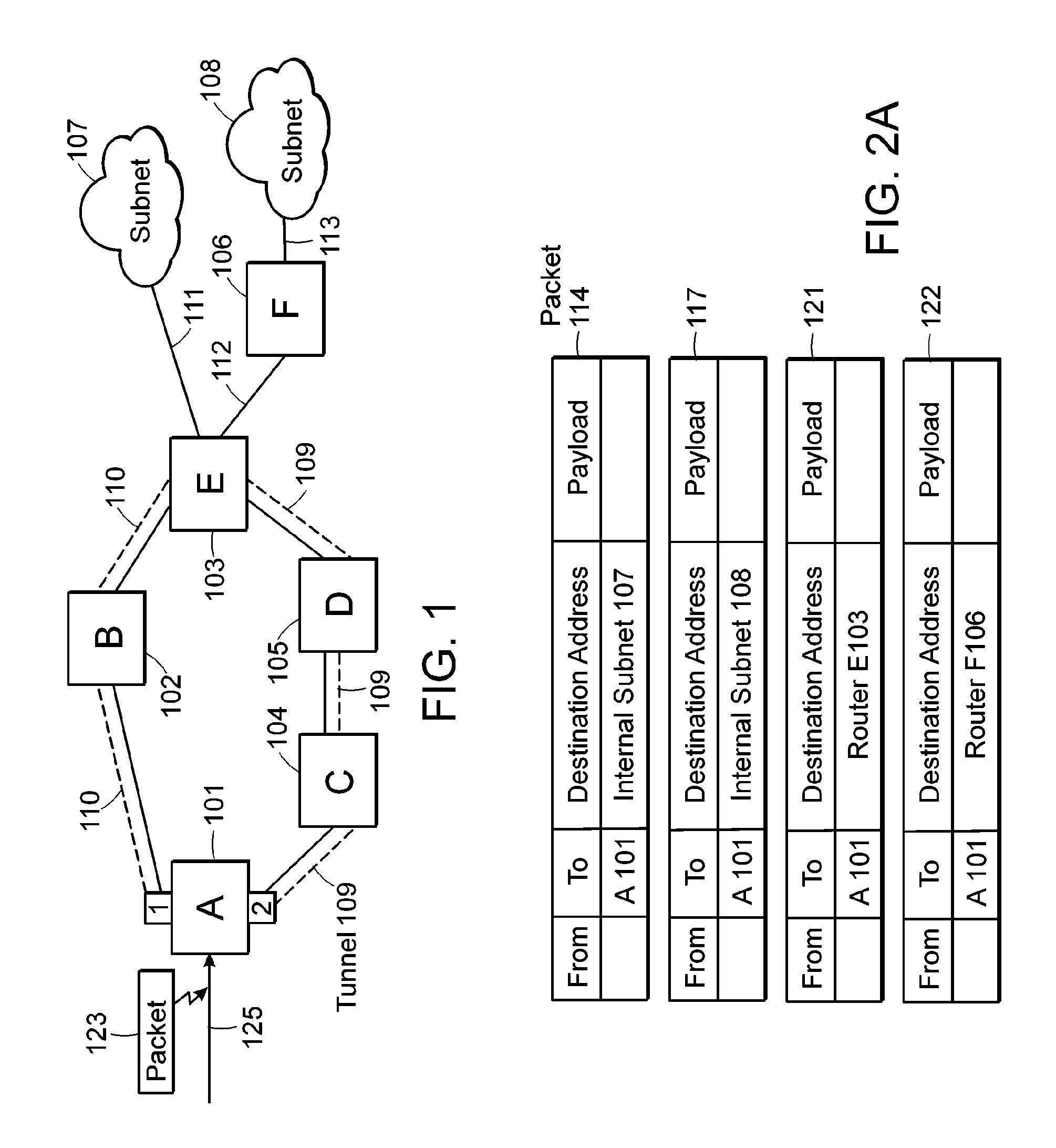
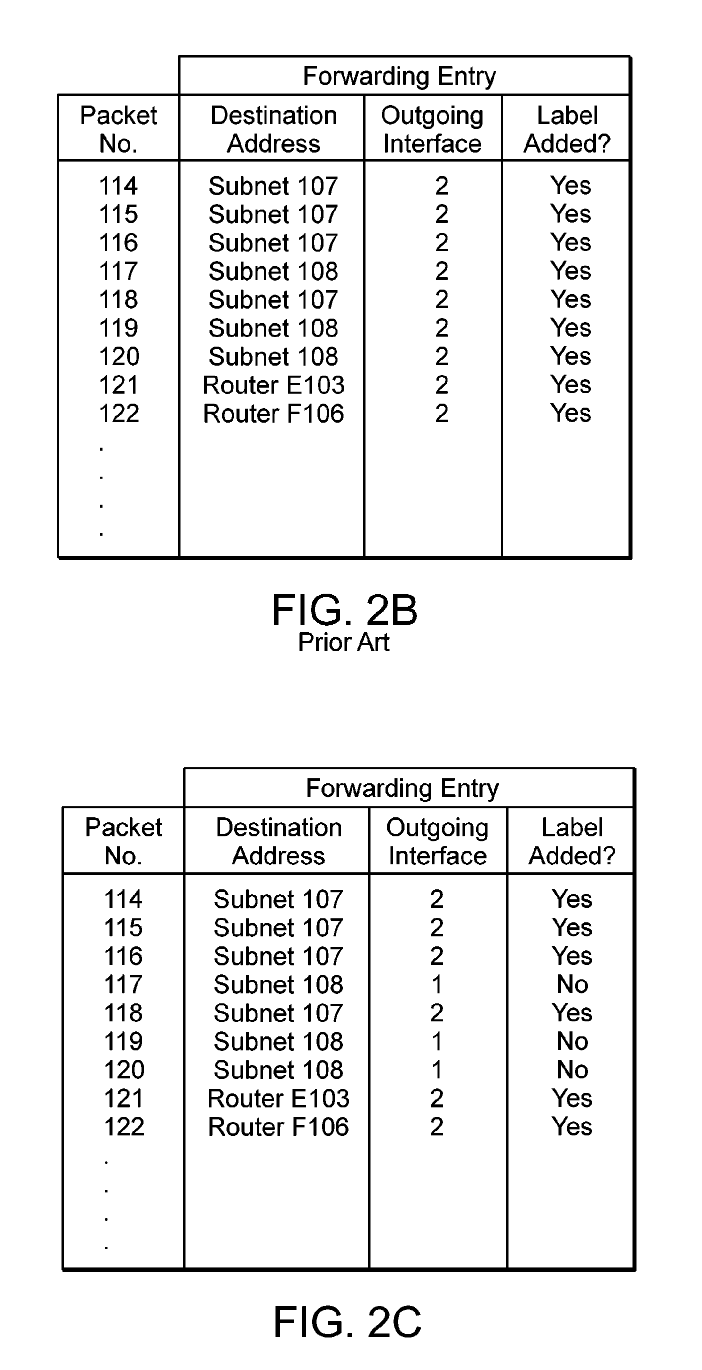
[0025]Referring to FIG. 1, there is depicted an information communication network including multiple routers A, B, C, D, E, and F as well as subnets 107 and 108 connected by various links. More specifically, ingress or head-end router A101 is shown with an input 125 which receives traffic or information or generic packet 123 (more detail about these packets is discussed in connection with FIG. 2A). Router A101 may have many output ports but shows only two output ports or interfaces 1 and 2 connected by link 110 to router B102 and link 109 to router C104 respectively. Link 109 is depicted as a tunnel and link 110 is depicted as other than a tunnel and could be a link based on OSPF...


PUM


Abstract

There is disclosed an apparatus and method for limiting tunnel traffic in a network. Traffic engineering tunnels are used to direct traffic along a predefined path, which may differ from the path that internet protocol (IP) routing would determine. Interior gateway protocol (IGP) cut through will allow the forwarding of all destinations downstream of a tunnel through the tunnel, without the operator needing to specify a forwarding equivalence class (FEC). But congestion in the tunnel and network instability may result from this approach. A solution to these problems is disclosed which limits the traffic in the tunnel to only that with destination addresses of the tunnel's egress router or nodes directly supported thereby. Other solutions are disclosed which allow tunnel traffic to nodes having destination addresses other than those being directly supported by the tunnel's egress router. All of these solutions are achieved in both pre-determined forwarding entry and dynamic packet-by packet embodiments.

Description

FIELD OF THE INVENTION[0001]The present invention relates generally to information communication networks and, more particularly, relates to limiting tunnel traffic in such networks.BACKGROUND OF THE INVENTION[0002]Computer networks are having more and more of an impact on human interaction with the passage of time. For one example, the Internet, which is currently used by only about 5% of worldwide human population, is being recognized as a boon to mankind. Accordingly, the Internet, is rapidly growing in usage on a global basis, is bringing a vast array of useful information to those members of our global village who are Internet users, and is fostering communication between diverse cultures located around the globe by way of the email system. As is widely known, the Internet has its foundation in globally-deployed computer networks. For other examples, one could cite rapidly growing non-Internet local area network (LAN) usages of computer networks in industry, academia, governmen...

Claims


Application Information

Patent Timeline
IPC IPC(8): G01R31/08G06F15/173H04L12/28H04L12/46H04L12/56
CPCH04L12/4633H04L45/12H04L45/50
Inventor HASS, BARRY L.FEDYK, DONALD
Owner AVAYA INC
Learn More