
Resistance welding of thermoplastics in aerospace structure

a technology of thermoplastic resin and aerospace structure, which is applied in the direction of climate sustainability, metal-working apparatus, layered product treatment, etc., can solve the problems of increasing the overall time required to fabricate each part, increasing the cost of organic resin composites, and affecting the quality of the finished produ

Inactive Publication Date: 2006-10-24
THE BOEING CO
View PDF203 Cites 18 Cited by
  • Summary
  • Abstract
  • Description
  • Claims
  • Application Information

AI Technical Summary

Benefits of technology

[0051]The present invention also relates to the wingbox formed according to the process. This wingbox has a lap joint structurally connecting the webs of the spars and ribs at their intersections. Both the spar and rib are a fiber-reinforced composite. The web lap joint is formed by the overlap of a tab on the spar web with a tongue on the rib web, the overlap defining a bond line. We form a thermoplastic weld at the joint, generally using a multistrip susceptor along the bond line and resistance heating.

Problems solved by technology

Organic resin composites, be they thermoplastics or thermosets, are expensive today.
The delay caused to heat and to cool the mass of the tools adds substantially to the overall time necessary to fabricate each part.
These delays are especially significant when the manufacturing run is low rate where the dies need to be changed frequently, often after producing only a few parts of each kind.
An autoclave has similar limitations; it is a batch operation.
The tooling in autoclave or hot press fabrication is a significant heat sink that consumes substantial energy.
Furthermore, the tooling takes significant time to heat the composite material to its consolidation temperature and, after curing the composite, to cool to a temperature at which it is safe to remove the finished composite part.
These attempts have shortened the time necessary to produce a composite part, but the cycle time for and cost of heating and cooling remain significant contributors to overall fabrication costs.
Designing and making tools to permit their active cooling increases their cost.
Such welding unduly impacts the preparation time and the cost for part fabrication.
It also ruined the facesheets (i.e., prohibited their reuse which added a significant cost penalty to each part fabricated with this approach).
Cast ceramic tools cost less to fabricate than metal tools of comparable size and have less thermal mass than metal tooling, because they are unaffected by the induction field.
Both mechanical fastening and adhesive bonding are costly, time consuming assembly steps that introduce excess cost even if the parts that are assembled are fabricated from components produced by an emerging, cost efficient process.
Mechanical fastening requires expensive hole locating, drilling, shimming, and fastener installation, while adhesive bonding often requires complicated surface pretreatments.
Access to both sides of the assembly is required in this process which limits its application.
Achieving a uniform, controllable temperature in the bondline, which is crucial to preparing a thermoplastic weld of adequate integrity to permit use of welding in aerospace primary structure, is difficult with those conventional susceptors.
Simple as the thermoplastic welding process sounds, and easy as it is to perform in the laboratory on small pieces, it becomes difficult to perform reliably and repeatably in a real factory on full-scale parts to build a large structure such as an airplane wing box.
The difficulty is in getting the proper amount of heat to the bondline without overheating the entire structure, and also in achieving intimate contact of the faying surfaces of the two parts at the bondline during heating and cooling despite the normal imperfections in the flatness of composite parts, thermal expansion of the thermoplastic during heating to the softening or melting temperature, flow of the thermoplastic out of the bondline under pressure (i.e., squeeze out), and then contraction of the thermoplastic in the bondline during cooling.
Therefore, it is difficult to obtain adequate heating at the bond line between two graphite or carbon fiber reinforced resin matrix composites relying on the susceptibility of the fibers alone as the source of heating in the assembly.
The overheating results in porosity in the product, delamination, and, in some case, destruction or denaturing of the resin.
Overheating the edges of the assembly can result in underheating the center, either condition leading to inferior welds because of non-uniform curing.
We found these susceptors difficult to reproduce reliably.
Parts of this magnitude are difficult to produce with perfect flatness.
These irregularities interfere with full surface area contact between the faying surfaces of the two parts and actually result in surface contact only at a few “high points” across the intended bondline.
Additional surface contact can be achieved by applying pressure to the parts to force the faying surfaces into contact, but full intimate contact is difficult or impossible to achieve in this way.
Applying heat to the interface by electrically heating the susceptor in connection with pressure on the parts tends to flatten the irregularities further, but the time needed to achieve full intimate contact with the use of heat and pressure is excessive, can result in deformation of the top part, and tends to raise the overall temperature of the “I” beam flanges to the softening point, so they begin to yield or sag under the application of the pressure needed to achieve a good bond.
Induction welding is limited, nevertheless, because there must be an appropriate oscillating magnetic field to create the eddy currents.
Rib-spar web joints typically are in the wrong plane for induction with existing equipment and these joints are of short span buried within the wingbox where arranging induction heating is troublesome.

Method used


Image

  • Resistance welding of thermoplastics in aerospace structure
  • Resistance welding of thermoplastics in aerospace structure
  • Resistance welding of thermoplastics in aerospace structure

Examples


Embodiment Construction

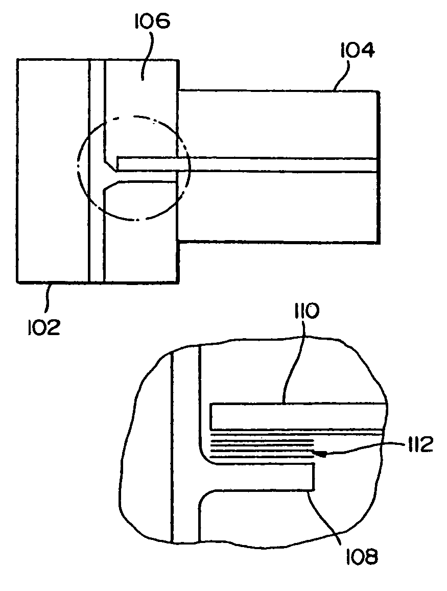
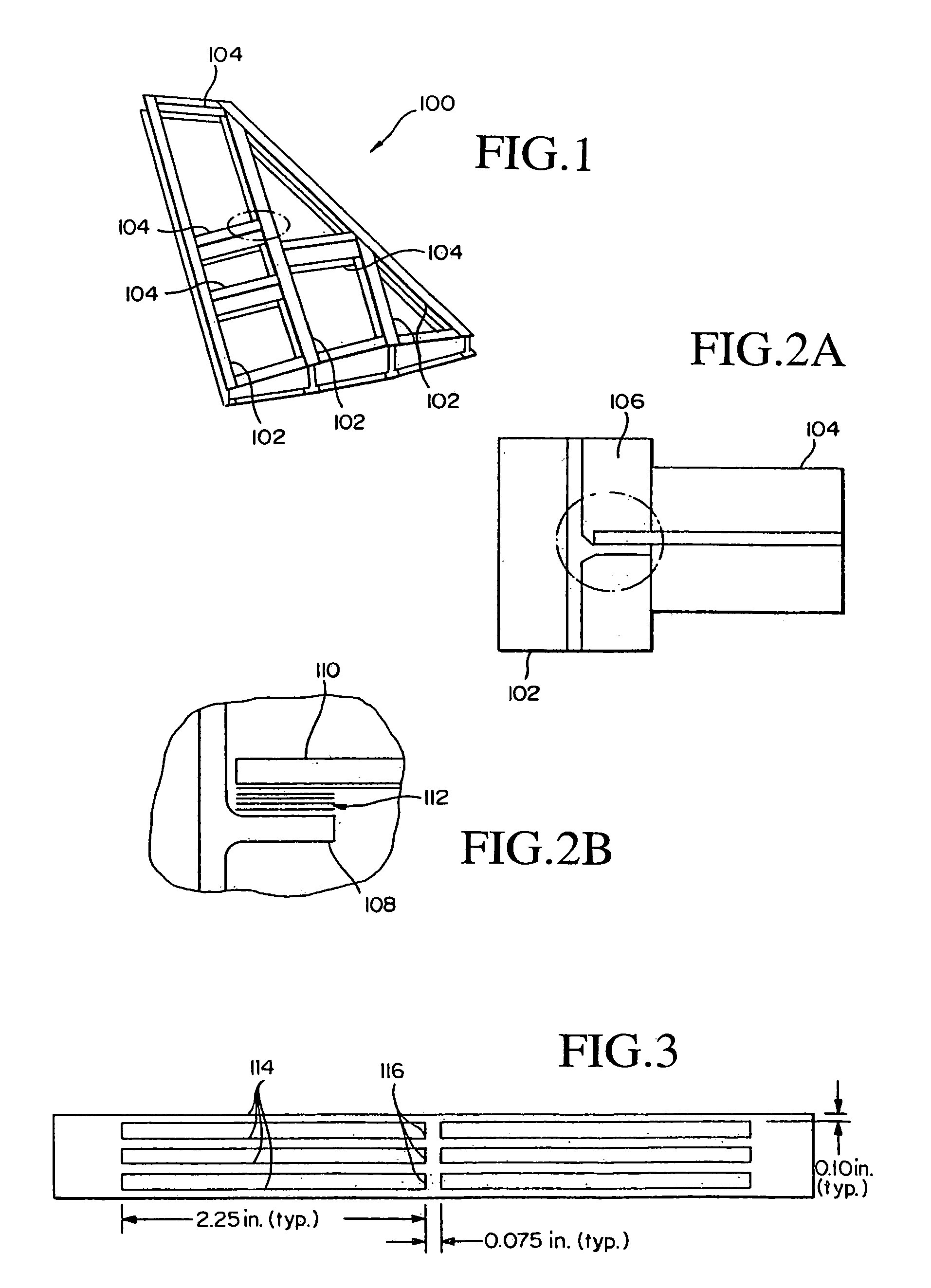
[0060]As shown in FIG. 1, a typical composite wingbox 100 designed for assembly without fasteners includes a plurality of longitudinal spars 102 with transverse ribs 104 interspersed along the run of the spars. The ribs 104 and spars 102 are joined at rib-spar web lap joints 106, which are schematically illustrated in FIG. 2. Each lap joint involves a tab 108 fabricated into the web of the spar and a tongue 110 at the end of the rib web. The cap of the rib is cut back at each joint so that the rib web can slide between the spar caps. As shown in FIG. 6, the welded wingbox 100 is completed by welding an upper skin 602 and lower skin 604 to the spar caps and rib caps.

[0061]The overlap between the tab and tongue defines the bondline where we position a multistrip susceptor 112 to form a weld or adhesive bond between the spar and rib webs by applying a suitable voltage across the bondline. The multistrip susceptor 112 includes a metal foil of the type shown in FIG. 3. The foil includes ...


PUM

PropertyMeasurementUnit
thickaaaaaaaaaa
thickaaaaaaaaaa
pressureaaaaaaaaaa

Abstract

Rib and spar webs are joined in a composite wingbox to eliminate fasteners by welding the webs along bondlines defined by overlapping sections of the webs. Heat to produce the weld is generally achieved resistively by connecting a multistrip susceptor positioned along the bond line to a current source, since the geometry makes it difficult to heat these web joints inductively. The wingbox is completed without fasteners by welding skins to the rib-spar wingbox.

Description

REFERENCE TO RELATED APPLICATIONS[0001]The present application is a continuation-in-part application based upon U.S. application Ser. No. 08 / 341,779, filed Nov. 18, 1994 now U.S. Pat. No. 5,599,472; which was a continuation-in-part application based upon U.S. patent application Ser. No. 08 / 169,655, filed Dec. 16, 1993 now U.S. Pat. No. 5,530,227; which was a continuation-in-part application of U.S. patent application Ser. No. 07 / 777,739, filed Oct. 15, 1991 now U.S. Pat. No. 5,410,132. U.S. patent application Ser. No. 08 / 341,779 also was a continuation-in-part application based upon U.S. patent application Ser. No. 08 / 092,050, filed Jul. 15, 1993 now U.S. Pat. No. 5,410,133; which was a divisional of U.S. patent application Ser. No. 07 / 681,004, filed Apr. 5, 1991, now U.S. Pat. No. 5,229,562; and finally, was a continuation-in-part application based upon U.S. patent application Ser. No. 08 / 151,433, filed Nov. 12, 1993 now U.S. Pat. No. 5,420,400. We incorporate these applications an...

Claims


Application Information

Patent Timeline
Patent Type & Authority Patents(United States)
IPC IPC(8): H05B6/10B21D26/055B22F3/105B29C33/06B29C35/08B29C65/00B29C65/34B29C65/36B29C70/44B29C70/54B64C3/18H05B6/02H05B6/14H05B6/36
CPCB21D26/055B29C66/91951B29C33/06B29C65/34B29C65/364B29C65/3644B29C66/634B29C66/721B29C70/44B29C70/542B64C3/18C22C47/068H05B6/365B22F3/105B29C66/91655B29C66/91645B29C66/91411B29C66/91443B22F2003/1046B22F2003/1053B22F2998/00B29C2035/0811B32B2309/62B29C65/3492B29C65/3676B29C65/3476Y02T50/433C22C47/20B29C66/7392B29C66/71Y02P10/25Y02T50/40B29K2071/00
Inventor MATSEN, MARC R.MCCARVILLE, DOUGLAS A.STEPAN, MICHAEL M.
Owner THE BOEING CO
Learn More