Head gimbal assembly method

a head gimbal and assembly method technology, applied in the direction of mechanical roughness/irregularity measurement, association of printed circuit non-printed electric components, instruments, etc., can solve the problems of complete hard drive failure, high cost, damage to the head or the media, etc., to simplify tooling, simplify tooling, and improve alignment

Inactive Publication Date: 2006-10-31
APPLIED KINETICS
View PDF30 Cites 41 Cited by
  • Summary
  • Abstract
  • Description
  • Claims
  • Application Information

AI Technical Summary

Benefits of technology

[0021]It is another object of the present invention to provide a method for attaching a head / slider to a circuited gimbal with one or more of the following advantages: without damaging the suspension; with improved alignment between the termination pads of the head / slider and the circuited gimbal; with simplified tooling; or with simplified tooling and improved substrate heating and control.
[0022]It is still yet another object of the present invention to provide a method for a dynamic electrical test of the read / write head without the suspension present with low cost and high throughput, thereby obviating the need to throw away a good suspension when a given head is found to be rejectable under DET test criteria.
[0024]It is another object of the present invention to reduce operator handling and other sources of ESD or EOS, which could otherwise damage the head element.
[0025]The present invention provides a method for assembling a head gimbal assembly useful in a hard disk drive and for testing such an assembly. In a method in accord with the present invention a head slider is mounted to a circuited gimbal in an automated assembly machine using an adhesive dispenser to dispense adhesive on a circuited gimbal, an automated pick and place machine to position a slider relative to the circuited gimbal, a vision system to precisely locate the slider and circuited gimbal with respect to each other, and the pick and place machine to place the slider on the circuited gimbal. The electrical contacts in the slider are then terminated to the traces or electrical leads of the circuited gimbal using an automated electrical termination machine.

Problems solved by technology

If the head is too far away from the media, signal loss will occur and if the head is too close to the media, the head could mechanically crash, that is, actually come into contact with the disk, resulting in damage to the head or the media and often a complete hard drive failure.
Many problems are encountered with the present process resulting in high costs and poor magnetic spacing tolerances.
One of the problems is that the present system is labor intensive.
This creates many potential opportunities for the generation of electrostatic charges, which can damage the components with an electrostatic discharge (ESD) or electrical overstress (EOS).
Another example of a problem relates to the electrical connection made between the head termination pads on the slider and the electrical interconnect or flex circuit running along the suspension after the slider is attached to the suspension.
These electrical connections are difficult to make for several reasons.
For example, the slider is positioned with respect to the gimbal load point and not necessarily the electrical leads on the suspension, which can cause the electrical connection to be difficult and unreliable.
In addition, because the intricate surface features of the head / slider and suspension make it difficult to hold in a fixture, the bonding process, which requires a significant force to achieve a good bond, often leads to damage of the suspension.
Current DET test procedures require that the head gimbal assembly be held in the loaded position at the correct magnetic spacing or Z-height with respect to the spinning testing disk, making both loading the assembly and automating this test difficult.
In addition, mechanical and head tolerances can cause a poor signal, making it difficult to discern the source of any poor performance.
Further, the DET results indicate that a head is bad and must be discarded, then the manufacturer must throw away not only the head / slider but also the suspension to which it is bonded.
This is a source for significant yield cost.
The act of bringing the suspension to its loaded position causes clamping and fixturing to be difficult as well as forces one to account for a pitch bias, because the loading is not at the suspension bond pad.
In addition, if the loading mechanism is not perfectly centered on the load beam, the act of loading can cause a roll bias in the angle measurement.
This reference problem resulted in an unpredictable bias between the measured static angles and the real static angles.
While the position target is to align the suspension load point to the designed location on the slider air bearing, tolerances make this a difficult task.
This technique alleviates the load point source of torque variation, but it does not address the torque from suspension, circuit, bond line parallelism and slider parallelism tolerances.
These techniques do not address torque from load point tolerances and the adhesive wedge is difficult to control, at best, thus it does not “bond out” the static angle tolerances.
U.S. Pat. Nos. 5,198,945 and 5,282,102 teach integrated flexure suspensions that reduce some load position errors, but do not address torque from static angle tolerance, bond line parallelism or slider parallelism.
It does not address load point, bond line parallelism or slider parallelism sources of torque.
Thus, inherently, this technique is difficult to automate and achieve high throughput.

Method used


Image

  • Head gimbal assembly method
  • Head gimbal assembly method
  • Head gimbal assembly method

Examples


Embodiment Construction

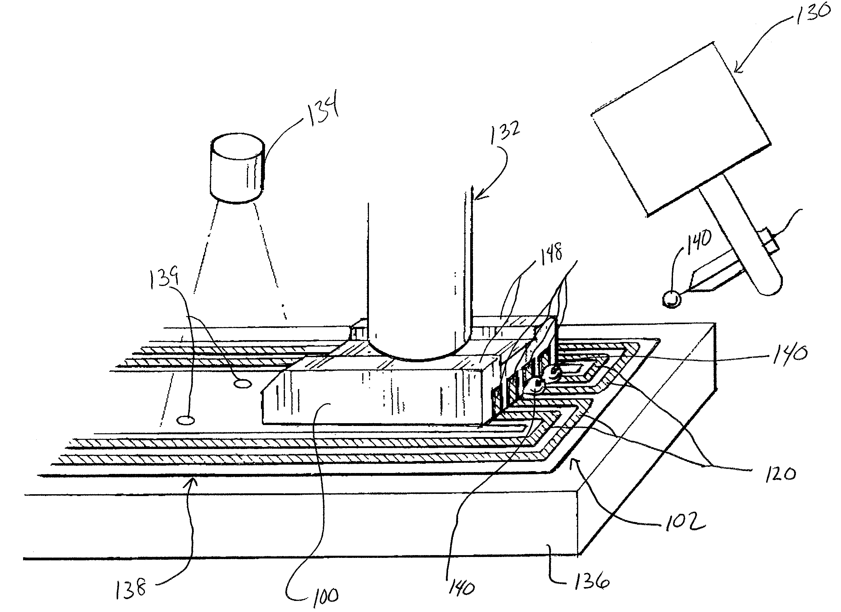
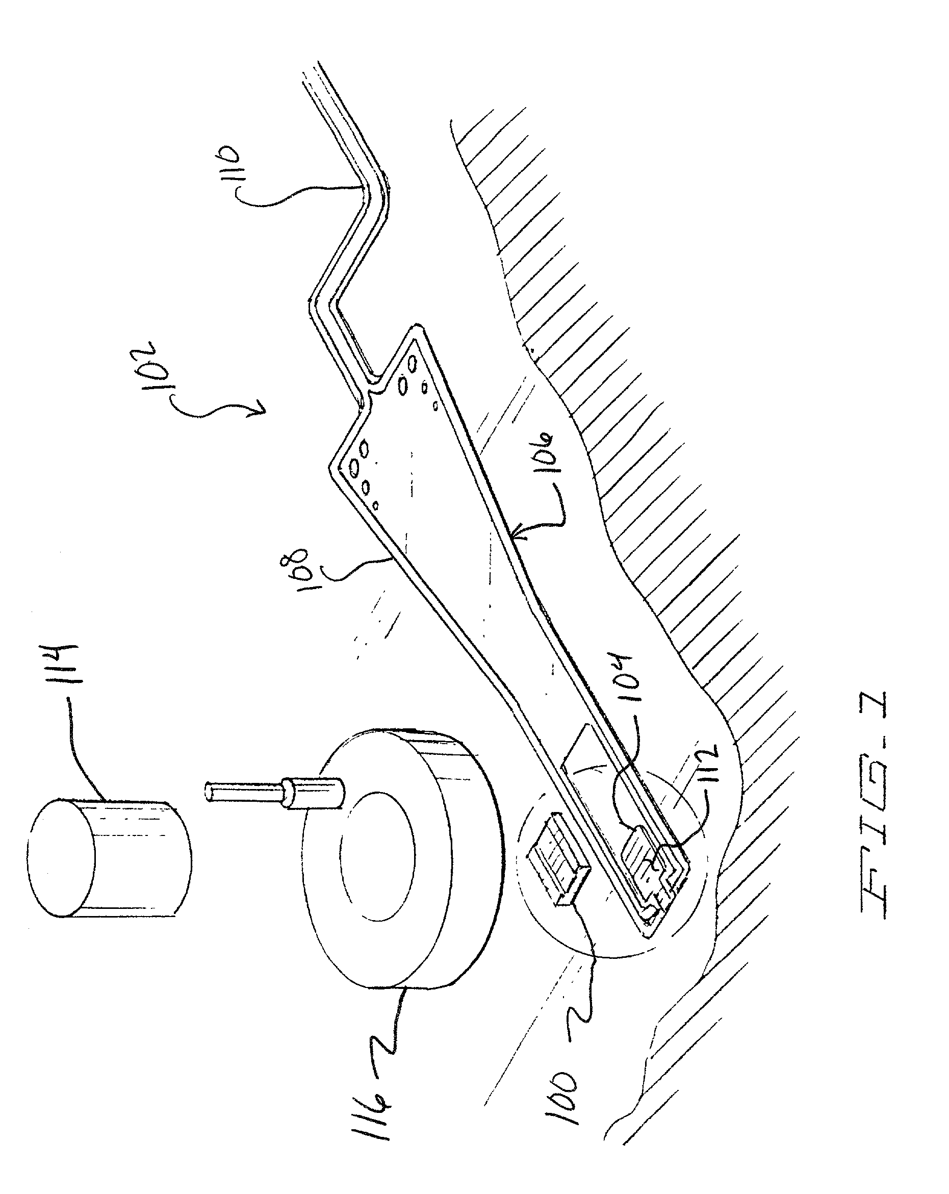
[0050]A solution to each of the above mentioned problems is a novel process flow combined with processing methods to accurately attach a read / write head / slider, make the electrical connection, perform a dynamic electrical test on the head prior to suspension attachment, measure static angles without loading the suspension and manage the final torque acting on the slider body to assure proper flying characteristics. This method will first be described generally and then more specifically to follow.

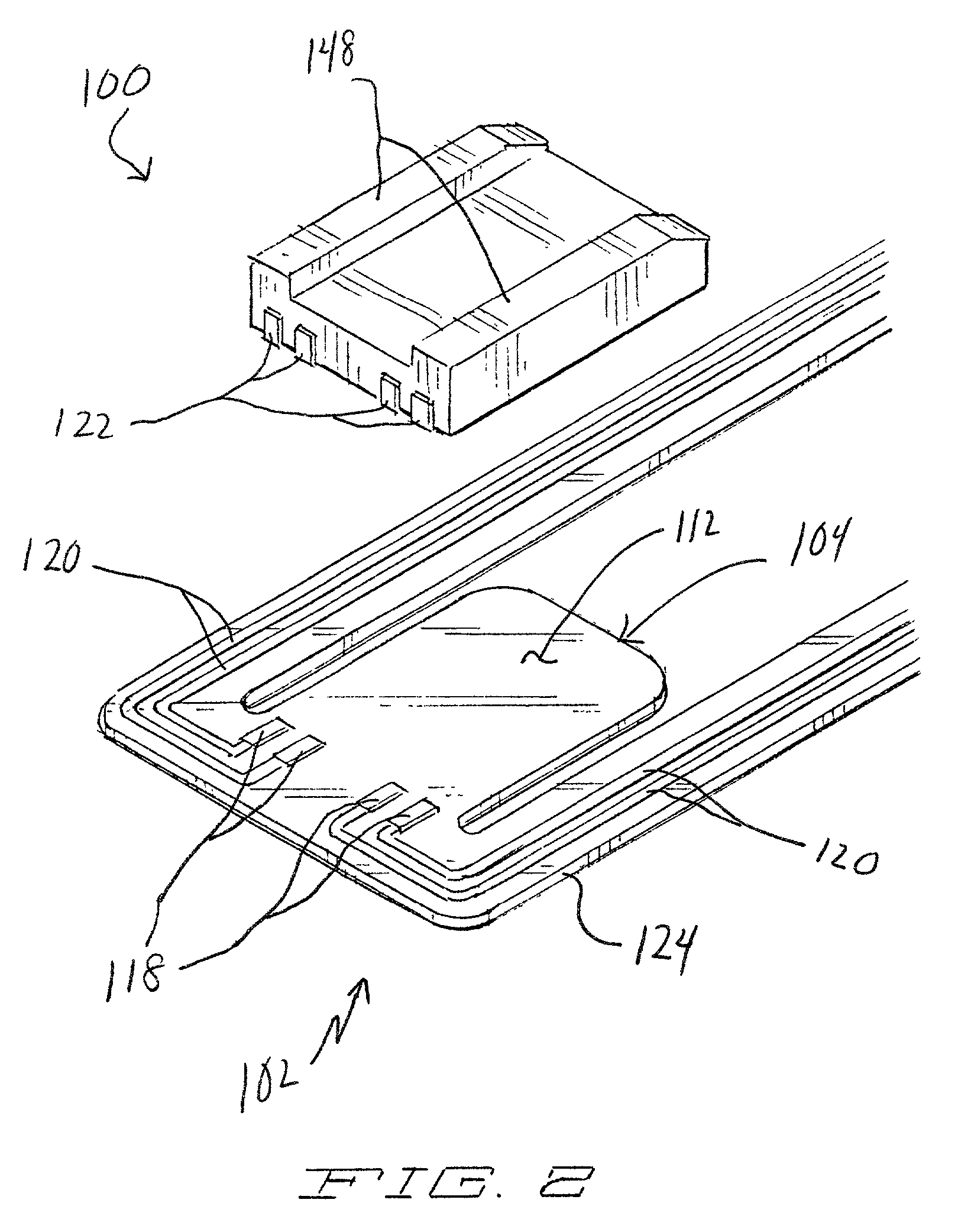
[0051]A tray or batch of head sliders are mounted to circuited gimbals in an automated pick and place machine, utilizing vision, stages, adhesive dispense and ultra-violet (UV) tacking. Such machines are known in the art and will be described generally herein. The circuited gimbals are of the type that includes integral traces, but are not completed suspension assemblies. The sliders are provided as individual pieces in their own respective package.

[0052]Once the sliders and circuited gimba...


PUM

PropertyMeasurementUnit
static angleaaaaaaaaaa
dynamic electrical testaaaaaaaaaa
stiffnessaaaaaaaaaa

Abstract

The present invention provides a method for assembling a head gimbal assembly useful in a hard disk drive and for testing such an assembly. In a method in accord with the present invention a head / slider is mounted to a circuited gimbal in an automated assembly machine. Following this step the head / slider circuited gimbal assembly will be subjected a dynamic electrical test with those head / slider circuited gimbal assemblies not passing being sorted from the lot. Following this step the head / slider circuited assembly will be attached to a suspension.

Description

[0001]This is a continuation of Application No. 09 / 410,602 filed Oct. 1, 1999 now abandoned.[0002]The present application is a continuation of U.S. Provisional Patent Application Ser. No. 60 / 102,860 , for Method for Manufacturing a Head Gimbal Assembly, filed Oct. 2, 1998, now abandoned the specification of which in incorporated herein in its entirety.FIELD OF THE INVENTION[0003]The present invention relates generally to assembly procedures used in the manufacture of hard disk drives and particularly to a method of assembling a head gimbal assembly and testing procedures used in evaluating the assembled component parts of the head gimbal assembly at various stages in the assembly process.BACKGROUND OF THE PRESENT INVENTION[0004]The hard disk drive is the principal device used for long term, bulk memory storage in today's computers. The hard disk drive includes a rotating disk and a head gimbal assembly that is attached to actuator arm in the disk drive and that is held thereby close...

Claims


Application Information

Patent Timeline
Patent Type & Authority Patents(United States)
IPC IPC(8): G11B5/127H04R31/00G11B5/48H05K1/18H05K3/32
CPCG11B5/4826H05K1/189H05K3/328Y10T29/49163Y10T29/49027Y10T29/49048Y10T29/49037Y10T29/49128Y10T29/49041Y10T29/49032
Inventor GIRARD, MARK T.JURGENSON, RYAN A.LIVERMORE, LEGAL REPRESENTATIVE, SUSAN JUNESWIFT, DAVID R.TRACY, JOSEPH P.LIVERMORE, DECEASED, ROGER R.
Owner APPLIED KINETICS
Why Eureka
Try Eureka