Solar thermal energy conversion system

a technology of solar thermal energy and conversion system, which is applied in the direction of refrigeration components, machines/engines, refrigeration machines, etc., can solve the problems of inefficiency of solar distillation design, failure to fully utilize the thermal energy trapped within the confines, and failure of designers to recognize the potential of stored energy to improve the efficiency of energy generating systems

Inactive Publication Date: 2006-10-31
BATTAH HAMMAM JAMIL GIRGIESS
View PDF3 Cites 14 Cited by
  • Summary
  • Abstract
  • Description
  • Claims
  • Application Information

AI Technical Summary

Benefits of technology

[0006]The solar thermal energy conversion system of the present invention stores solar energy in water in the form of heat. The system utilizes the accumulated solar generated heat as well as the heat of condensation to increase the temperature of water internally of perimeter insulation surrounding a plurality of integrated solar cells.

Problems solved by technology

Existing systems, although fulfilling their primary design purpose, often fail to fully utilize the thermal energy trapped within their confines.
In many systems, this is a reflection on the inefficiency of design for solar distillation.
In other systems, however, this inefficient approach represents a failure of designers to recognize the potential of the stored energy to improve the efficiency of energy generating systems.
In order for significant temperature differences to be utilized, existing systems must often be located (or have access to) offshore and are therefore exposed to the ravages of nature.
This contributes significant costs and inefficiencies to these systems and often requires their location at a position distant from the potential users of the generated energy.
Although considerable effort has been expelled to extract as much energy as possible from this temperature range, the potential is limited.
In addition to the thermal inefficiencies, existing OTEC systems often suffer from other disadvantages such as biofouling.
This contributes both expense and additional inefficiencies to existing systems.
Processes such as reverse osmosis can minimize the effects of biofouling, but contribute their own complexities to the systems.
The problem of biofouling can exist for a wide variety of energy generating systems that attempt to utilize sea water as an active ingredient.

Method used


Image

  • Solar thermal energy conversion system
  • Solar thermal energy conversion system
  • Solar thermal energy conversion system

Examples


Embodiment Construction

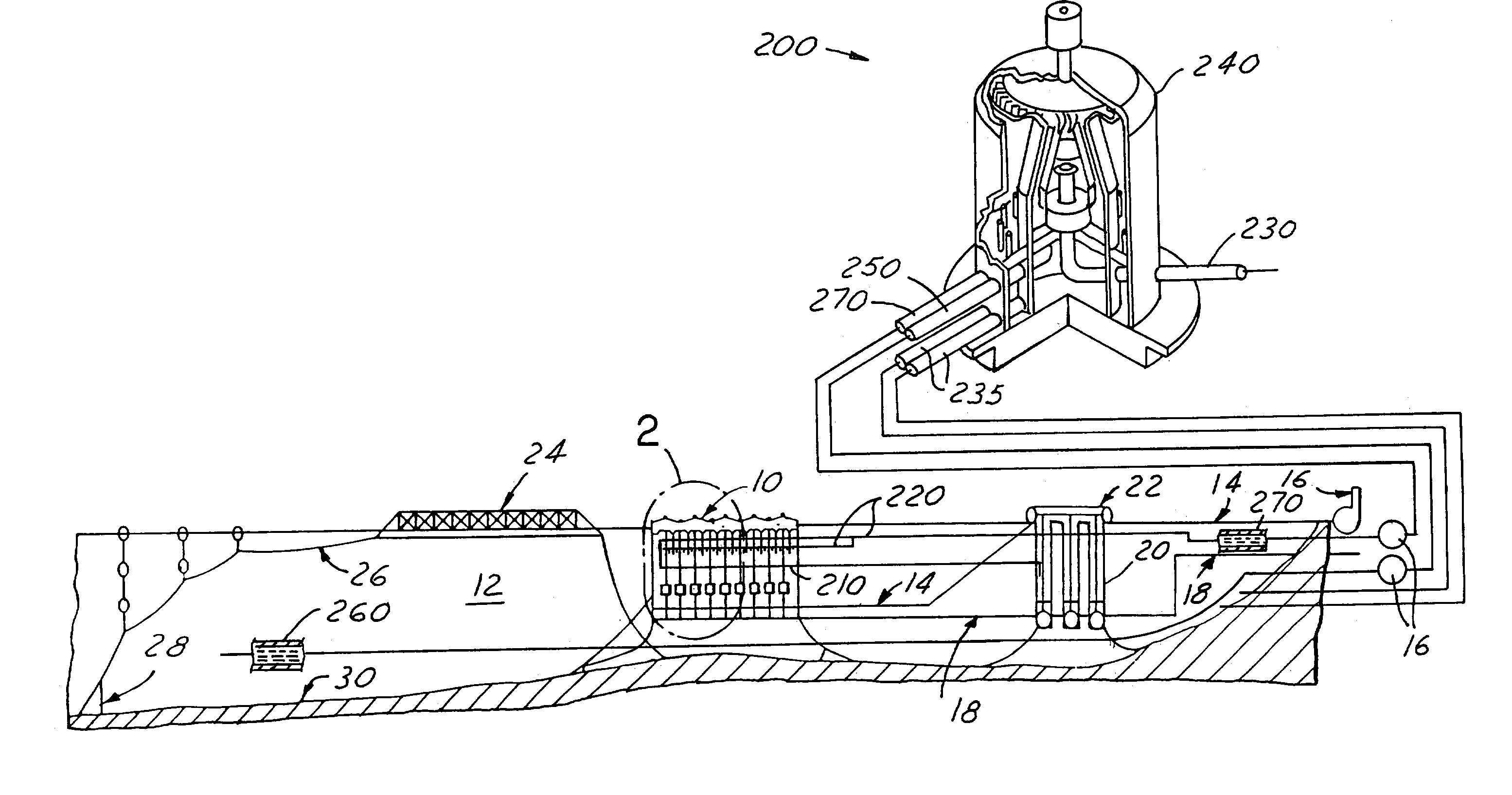
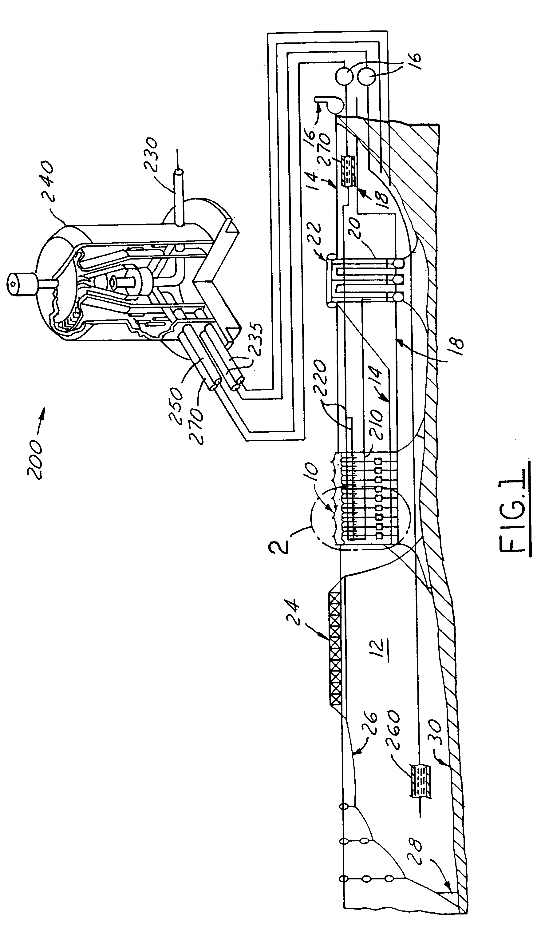
[0021]As seen in FIG. 1, a solar energy conversion system 8 is provided that utilizes a plurality of interconnected solar cells 10 adapted to float over a body of water 12. The body of water 12 may represent salt water or fresh water. Additionally, although the body of water 12 is contemplated to encompass any water mass either natural or man-made, the body of water 12 is preferably one located in a position between ±37 latitudes wherein the energy storage potential of the solar energy conversion system 8 can be fully utilized. When the solar thermal energy conversion system 8 is deployed over a body of water 12 that is subject to wave action, a wave breaker 24 may be employed to protect the solar cells 10 from the waves. Suitable cables 26 and anchors 28 position the system 8 relative to the sea bed 30.

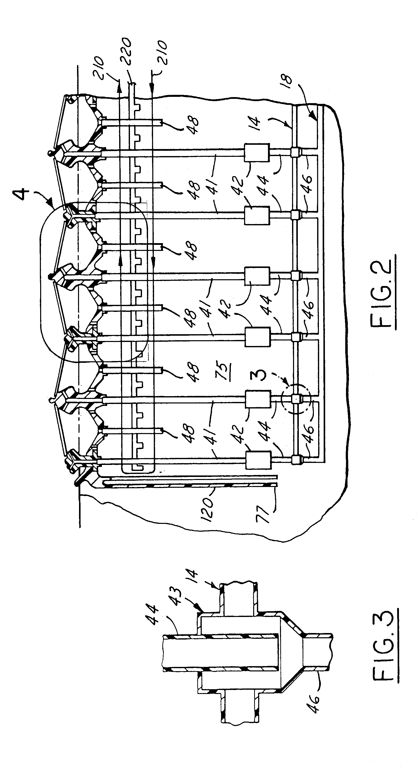
[0022]As seen in FIGS. 2 and 4, each solar cell 10 is made of insulating material, for example, polyurethane foam encapsulated by PVC or the like to preclude attack by salt water. Ea...


PUM


Abstract

A solar cell floats over a body of saline water. A submerged fresh water collection system underlies the cell. A partial vacuum is created in the solar cell for drawing water vapor from the cell to the collection system. Water vapor is condensed in a condenser disposed between the cell and the collection system. Heat generated by the condensation of water vapor is utilized to heat the salt water, which rises upwardly to replace the salt water vaporized in the cell. The fresh water from the fresh water collection system is routed under the cell such that it becomes thermally enriched. The thermally enriched fresh water is provided to a power generator to improve efficiency.

Description

TECHNICAL FIELD[0001]The present invention relates generally to a solar energy conversion system and more particularly to a solar thermal energy conversion system for power generation.BACKGROUND OF THE INVENTION[0002]Solar distillation systems are known that utilize solar energy stored in sea water to assist in the production of fresh water. These systems, however, are generally directed solely at the evaporation of sea water and the subsequent condensation of fresh water. Existing systems, although fulfilling their primary design purpose, often fail to fully utilize the thermal energy trapped within their confines. In many systems, this is a reflection on the inefficiency of design for solar distillation. In other systems, however, this inefficient approach represents a failure of designers to recognize the potential of the stored energy to improve the efficiency of energy generating systems.[0003]The concept of utilizing the thermal properties of sea water in an effort to generate...

Claims


Application Information

Patent Timeline
Patent Type & Authority Patents(United States)
IPC IPC(8): F03G6/00F03G7/05F24J2/52H01L31/00
CPCF03G6/001F03G7/05F24J2/5267C02F2103/08F05B2240/93Y02E10/34Y02E10/46Y02E10/47Y10S159/903Y10S159/904Y02A20/142F24S20/70Y02E10/30
Inventor BATTAH, HAMMAM JAMIL GIRGIESS
Owner BATTAH HAMMAM JAMIL GIRGIESS
Why Eureka
Try Eureka