
Optical information recording medium

a technology of optical information and recording medium, which is applied in the field of optical information recording medium, can solve the problems of reducing reflectivity, deteriorating the shape of marks to be recorded, and reducing c/n and jitter, and achieves excellent recording properties, desirable jitter, and high density

Inactive Publication Date: 2006-10-31
FUJIFILM HLDG CORP +1
View PDF79 Cites 19 Cited by
  • Summary
  • Abstract
  • Description
  • Claims
  • Application Information

AI Technical Summary

Benefits of technology

[0017]The present invention aims to solve such problems as those described above. Thus, an object of the invention is to provide a high density optical information recording medium having excellent recording properties, to provide an optical information recording medium having desirable jitter and a disc surface with improved scratch resistance, and to provide an optical information recording medium having an organic dye-containing recording layer, wherein the optical information recording medium is of a DVR-Blue type and excellent without suffering reproduction deterioration, RF output decrease, C / N decrease, and jitter deterioration.

Problems solved by technology

In such a case, a laser spot becomes small and a distance between the pickup and the medium (a working distance) is narrowed, so that a problem occurs in that a roughness of the medium surface, which scarcely has any effect in the case of a conventional optical recording medium, does have effects on this medium.
In other words, if the slight unevenness of the recording medium surface is significant, diffused reflection of light from the medium surface occurs, resulting in problems such as decreased reflectivity, deterioration in the shape of marks to be recorded, and lowered C / N and jitter.
Accordingly, the disc surface is easily scratched causing errors at the time of reproduction (playback).
The recording tracks, however, are so close to one another that problems such as cross erasing and cross stroking affecting tracks already recorded by the laser are apt to take place when recording is carried out in tracks adjacent to the already recorded tracks.
Furthermore, conversion to DVD-ROM is difficult.
Therefore, durability with respect to repeat reproduction becomes an issue.
When the reproduction output is lowered, however, the reflectivity is decreased, resulting in RF output decrease, C / N decrease, and jitter deterioration.
Such a structure, therefore, leads to problems including RF output decrease, C / N decrease, and jitter deterioration.

Method used


Image

  • Optical information recording medium
  • Optical information recording medium
  • Optical information recording medium

Examples


example 1

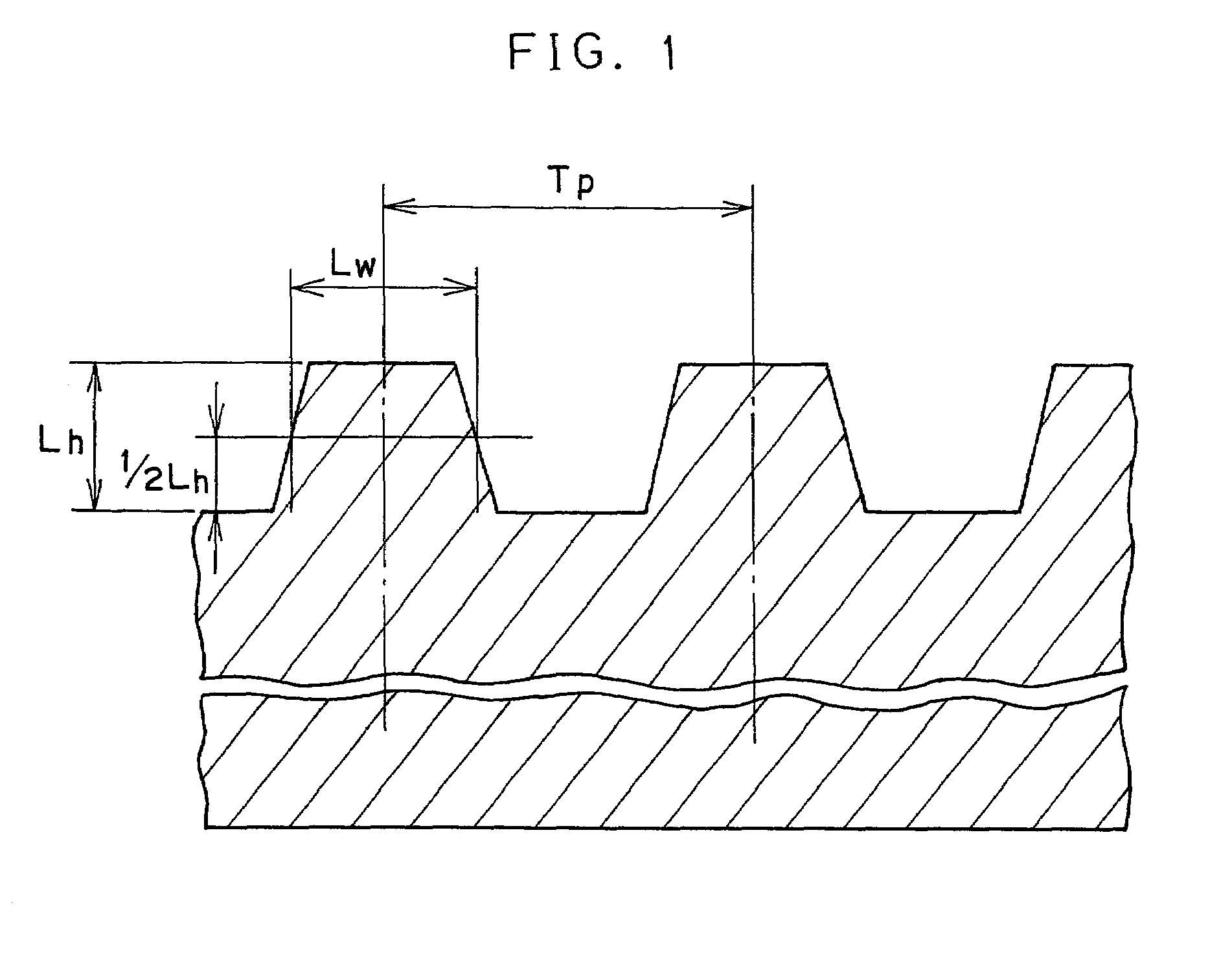
[0182]Using a substrate made of extrusion molded polycarbonate resin (trade name: Panlite AD 5503, polycarbonate manufactured by Teijin Limited) and having a thickness of 1.1 mm and a spiral groove with a diameter of 120 mm (the depth 100 nm; the width 0.120 μm, and the track pitches 300 nm), Ag was sputtered on the face of the substrate having the groove to form a light reflective layer with a film thickness of 100 nm, and after that, a dye coating solution produced by dissolving an Orasol Blue GN (manufactured by Ciba Speciality Chemical Co.; the maximum absorption wavelength: 340 nm) as a dye A in 2,2,3,3-tetrafluoropropanol by mixing them by ultrasonic wave vibration for 2 hours was applied to the resulting substrate by a spin coating method while the rotation speed being changed from 300 rpm to 4,000 rpm under the conditions of 23° C. and 50% RH. After that, the substrate was kept at 23° C. and 50% RH for 1 hour and further an ultraviolet ray-curable adhesive (SD-347, manufactu...

example 2

[0208]An optical information recording medium was produced in the same manner as Example 1 except that a polycarbonate sheet B (SRa1: 2.5 nm, SRa2: 1.0 nm, and the thickness: 0.07 mm) was used in place of the polycarbonate sheet A used in Example 1 and the same measurement and evaluation were carried out. The results were shown in Table 1.

example 3

[0209]An optical information recording medium was produced in the same manner as Example 1 except that a polycarbonate sheet C (SRa1: 1.0 nm, SRa2: 2.2 nm, and the thickness: 0.07 mm) was used in place of the polycarbonate sheet A used in Example 1 and the same measurement and evaluation were carried out. The results were shown in Table 1.


PUM

PropertyMeasurementUnit
surface average roughnessaaaaaaaaaa
thicknessaaaaaaaaaa
thicknessaaaaaaaaaa

Abstract

The present invention provides an optical information recording medium that includes a substrate including a groove with a track pitch of 200 to 400 nm and a groove depth of 20 to 150 nm and having successively disposed thereon a light reflecting layer, a recording layer containing a dye in which information is recorded by irradiation with a laser beam having a wavelength of no greater than 450 nm, an adhesive layer, and a cover layer with a thickness of 0.01 to 0.5 mm. A surface of the optical information recording medium on a side disposed with the cover layer has a center surface average roughness (SRa1) of no greater than 3.0 nm when measured over a large surface area and a center surface average roughness (SRa2) of no greater than 3.0 nm when measured over a minute surface area.

Description

BACKGROUND OF THE INVENTION[0001]1. Field of the Invention[0002]The present invention relates to an optical information recording medium, and particularly to an optical information recording medium rewritable in a heat mode.[0003]2. Description of the Related Art[0004]With the beginning of BS (Broadcast Satellite) digital broadcasting in high definition television (HDTV) image quality just around the corner, the development of large capacity recording media, capable of recording BS digital broadcasting in HDTV image quality for about 2 hours, is advancing. In an optical disc for a violet laser beam source, regarded as having high potential as the next generation of optical disc, a recording layer is formed on a substrate by coating a thin cover layer having a thickness of 0.1 mm to 0.3 mm. In a system using the optical disc, the laser beam is throttled using an objective lens with a high numerical aperture (hereinafter referred simply as to NA) of 0.65 or higher for a pickup, and re...

Claims


Application Information

Patent Timeline
Patent Type & Authority Patents(United States)
IPC IPC(8): G11B7/24G11B7/007G11B7/24079G11B7/246G11B7/2467G11B7/247G11B7/2472G11B7/2478G11B7/253G11B7/2532G11B7/2533G11B7/2534G11B7/2535G11B7/258G11B7/259
CPCG11B7/24G11B7/24079G11B7/246G11B7/26G11B7/2467G11B7/2472G11B7/2478G11B7/248G11B7/2532G11B7/2533G11B7/2534G11B7/2535G11B7/259Y10S430/146
Inventor KAKUTA, TAKESHISAITO, SHINJIISHIDA, TOSHIOOZAWA, TAKAKODOUSHITA, HIROAKI
Owner FUJIFILM HLDG CORP
Learn More