
Natural gas dehydration apparatus

a technology of natural gas and dehydration apparatus, which is applied in the direction of chemistry apparatus and processes, separation processes, dispersed particle separation, etc., can solve the problems of reducing, but not eliminating, btex and other, additional gaseous or aqueous waste stream, etc., and achieve the reduction of the dew point of the treated natural gas and the water content of the regenerated glycol

Inactive Publication Date: 2006-11-07
MEMBRANE TECH & RES
View PDF29 Cites 6 Cited by
  • Summary
  • Abstract
  • Description
  • Claims
  • Application Information

AI Technical Summary

Benefits of technology

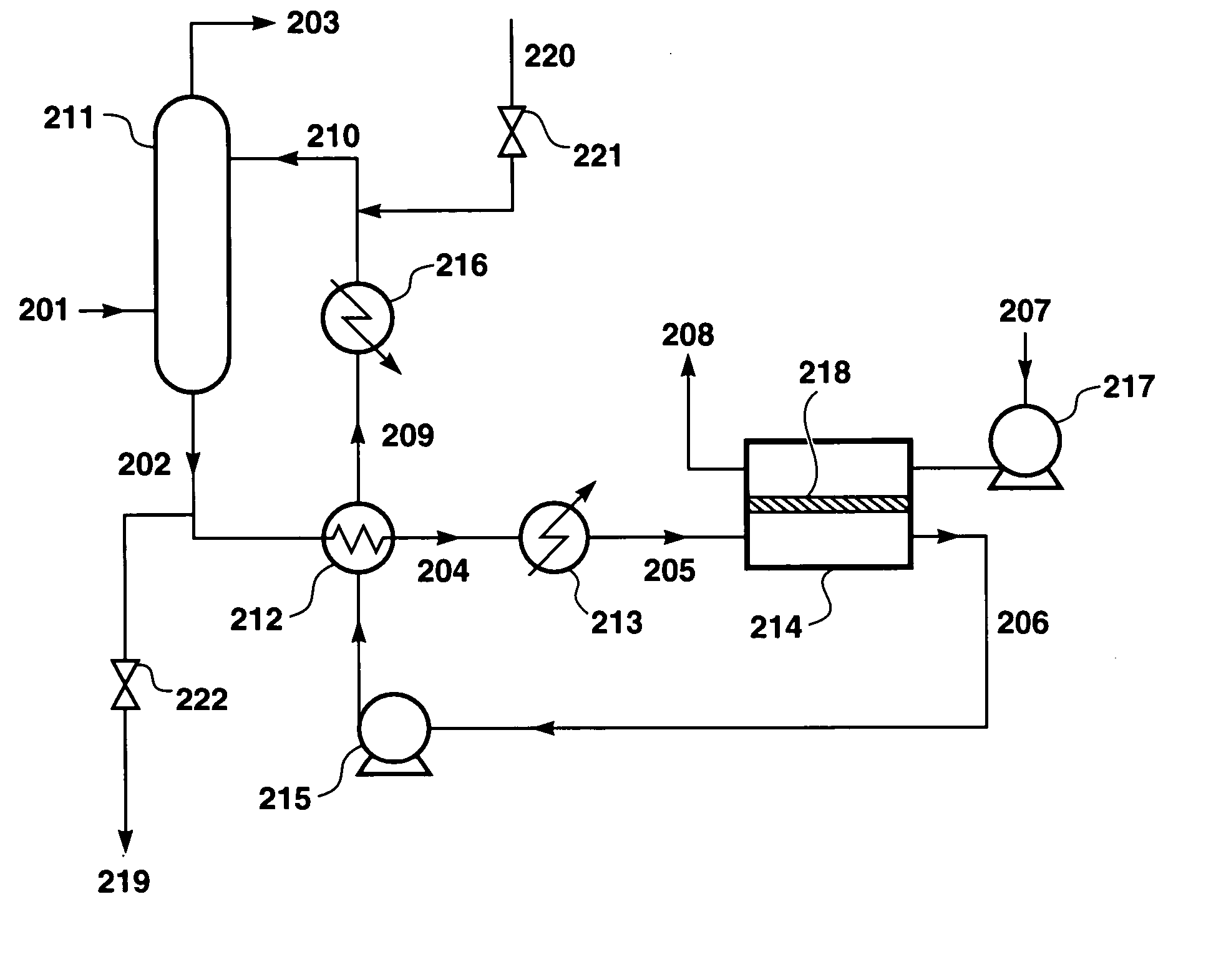
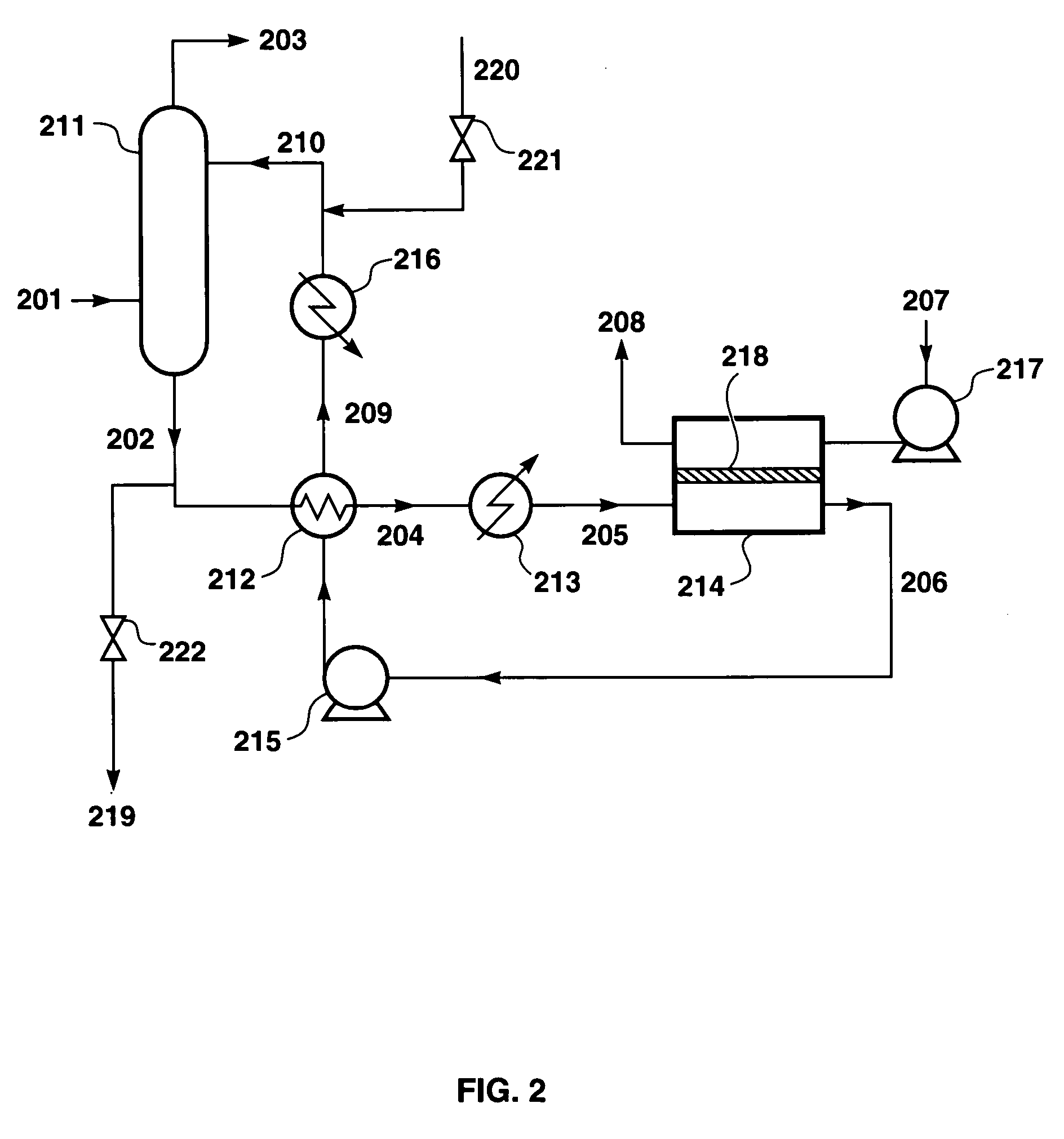
[0057]By operating at such a feed temperature, and optionally passing a sweep gas, such as air, to lower the partial pressure of water vapor on the permeate side, it is possible to reduce the water content of the regenerated glycol to a low level, such as 1 wt %, 0.5 wt %, 0.2 wt % or even less. Thus, the glycol that is returned to the absorption column is drier than is the case when glycol is regenerated in a conventional reboiler, which typically reduces the water content to no lower than about 2 wt %.
[0058]The use of drier glycol in the absorption step means that the dew point of the treated natural gas can be reduced compared with conventional dehydration. The dehydrated gas may have a water dew point as low as −20° C., −30° C. or lower, for example.
[0060]The membranes provide high separation factors in favor of water over all organic components. Thus, the BTEX concentration in the water vapor permeate stream is generally well below 1,000 ppmv, and typically no more than about 100 ppmv, and the glycol content is negligibly small, such as less than 50 ppmv. These low levels enable dehydrators to operate so as to meet various requirements and regulations in many regions for HAPs emissions. Thus, in general, the permeate stream may be safely discharged to the atmosphere.

Problems solved by technology

Unfortunately, this heating also vaporizes hydrocarbons that have been sorbed into the glycol, and these are expelled, along with the water vapor, in the hot overhead vent stream from the still column.
They can also reduce, but do not eliminate, BTEX and other HAP air emissions through the additional treatment step.
However, most of these processes produce an additional gaseous or aqueous waste stream that requires on-site or off-site attention such as incineration, disposal, or further treatment.
Despite these efforts, a cost-effective regeneration technology that truly minimizes or eliminates HAP emissions has not been developed.

Method used


Image

  • Natural gas dehydration apparatus
  • Natural gas dehydration apparatus
  • Natural gas dehydration apparatus

Examples


example 1

[0132]An experiment was performed to determine the water flux of a zeolite membrane module (Mitsui USA, New York), containing 70 cm2 of membrane area. The zeolite module was tested at 100° C. with a triethylene glycol mixture containing 5 wt % water. A nitrogen sweep was provided on the permeate side. The flow rate of the feed solution was 0.25 gpm. The results are shown in Table 1.

[0133]

TABLE 1Vapor Pressure-NormalizedTemperatureN2 SweepWater FluxWater FluxExpt. #(° C.)(L / min)(g / m2 · h)(g / m2 · h · psid)1985.2602321005.013043

example 2

[0134]Two series of experiments similar to those of Example 1 were carried out with a silica membrane module (Pervatech, Enter, The Netherlands), containing 55 cm2 of membrane area. The silica module was tested with triethylene glycol mixtures containing 0.7–5.5 wt % water. The mixture also contained 0.5 wt % hexane and 0.5 wt % toluene. The first series of experiments was carried out at about 130° C., the second set at about 150° C. The upper temperature was the limit of the test system, determined by the heat transfer capacity available in the system. The feed flow rate was 0.5 gpm. A nitrogen sweep at a flow rate of 2.5 L / min was provided on the permeate side. The results of the experiments are shown in FIG. 3, which plots the water flux of the membrane as a function of the feed water concentration.

[0135]In all experiments the permeate was essentially pure water with hexane and toluene present in the low ppm range. FIG. 3 shows that the flux increases with the water concentration...

example 3

[0136]Permeate samples were collected during the silica membrane pervaporation experiments of Example 2, and were analyzed for their hexane and toluene content by GC. The very low permeation rates of toluene and hexane made accurate measurements with our equipment difficult. However, representative data are shown in Table 2.

[0137]

TABLE 2FeedEquilibriumVapor Pressure-Concen-VaporPermeateNormalizedtrationPressureConcen-FluxComponent(wt %)(psia)tration(g / m2 · h · psid)Water5.421.699.99+ wt %35Triethylene93.60.13none—GlycoldetectedToluene0.51.518 ppmw0.009Hexane0.58.722 ppmw0.002

[0138]The highest toluene concentration measured was 50 ppmw (ppm by weight) and the highest hexane concentration was 30 ppmw; many samples contained significantly less. Based on the highest concentrations measured at 157° C., the toluene pressure-normalized flux is on the order of 10−2 g / m2·h·psid, and the n-hexane flux is on the order of 10−3 g / m2·h·psid. These fluxes are orders of magnitude lower than the wat...


PUM

PropertyMeasurementUnit
Temperatureaaaaaaaaaa
Flow rateaaaaaaaaaa

Abstract

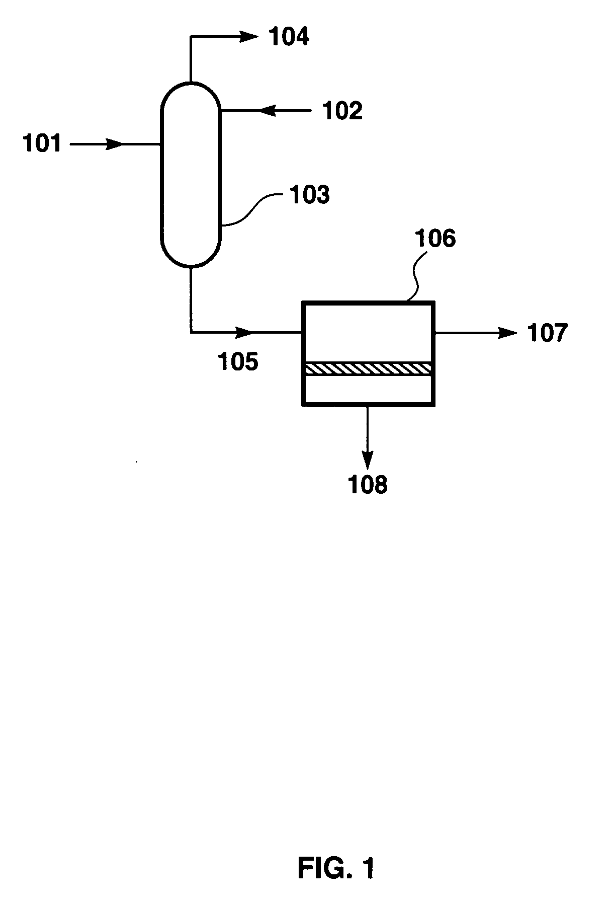
A process and corresponding apparatus for dehydrating gas, especially natural gas. The process includes an absorption step and a membrane pervaporation step to regenerate the liquid sorbent.

Description

[0001]This application is a continuation-in-part of application Ser. No. 10 / 280,147, filed Oct. 25, 2002 now U.S. Pat. No. 6,789,288.[0002]This invention was made in part with Government support under SBIR award number DE-FG03-01ER83272, awarded by the Department of Energy. The Government has certain rights in this invention.FIELD OF THE INVENTION[0003]The invention is a process and apparatus for dehydrating gas, such as natural gas. The process uses an absorption system to dehydrate the gas, and a membrane pervaporation unit to regenerate the water-laden desiccant.BACKGROUND OF THE INVENTION[0004]Natural gas as obtained from the well contains water vapor. Before the gas can be passed to the pipeline, it must be dried to prevent problems such as hydrate or ice formation or corrosion.[0005]Glycol dehydration, which is simple and inexpensive, is currently the most widely used method of dehydrating natural gas. The estimated number of glycol dehydration systems operating in the United ...

Claims


Application Information

Patent Timeline
IPC IPC(8): B01D53/14B01D53/22B01D53/26
CPCB01D53/1425B01D53/263
Inventor WIJMANS, JOHANNES GNG, ALVINMAIRAL, ANURAG P
Owner MEMBRANE TECH & RES
Learn More