
Method and apparatus for improving PET detectors

a technology of detectors and pet bodies, applied in tomography, instruments, x/gamma/cosmic radiation measurement, etc., can solve problems such as sticking differences between disciplines, and achieve the effects of high programmable computing capability, high spatial resolution information accuracy, and accurate total energy measuremen

Active Publication Date: 2006-11-07
CROSETTO DARIO B
View PDF39 Cites 41 Cited by
  • Summary
  • Abstract
  • Description
  • Claims
  • Application Information

AI Technical Summary

Benefits of technology

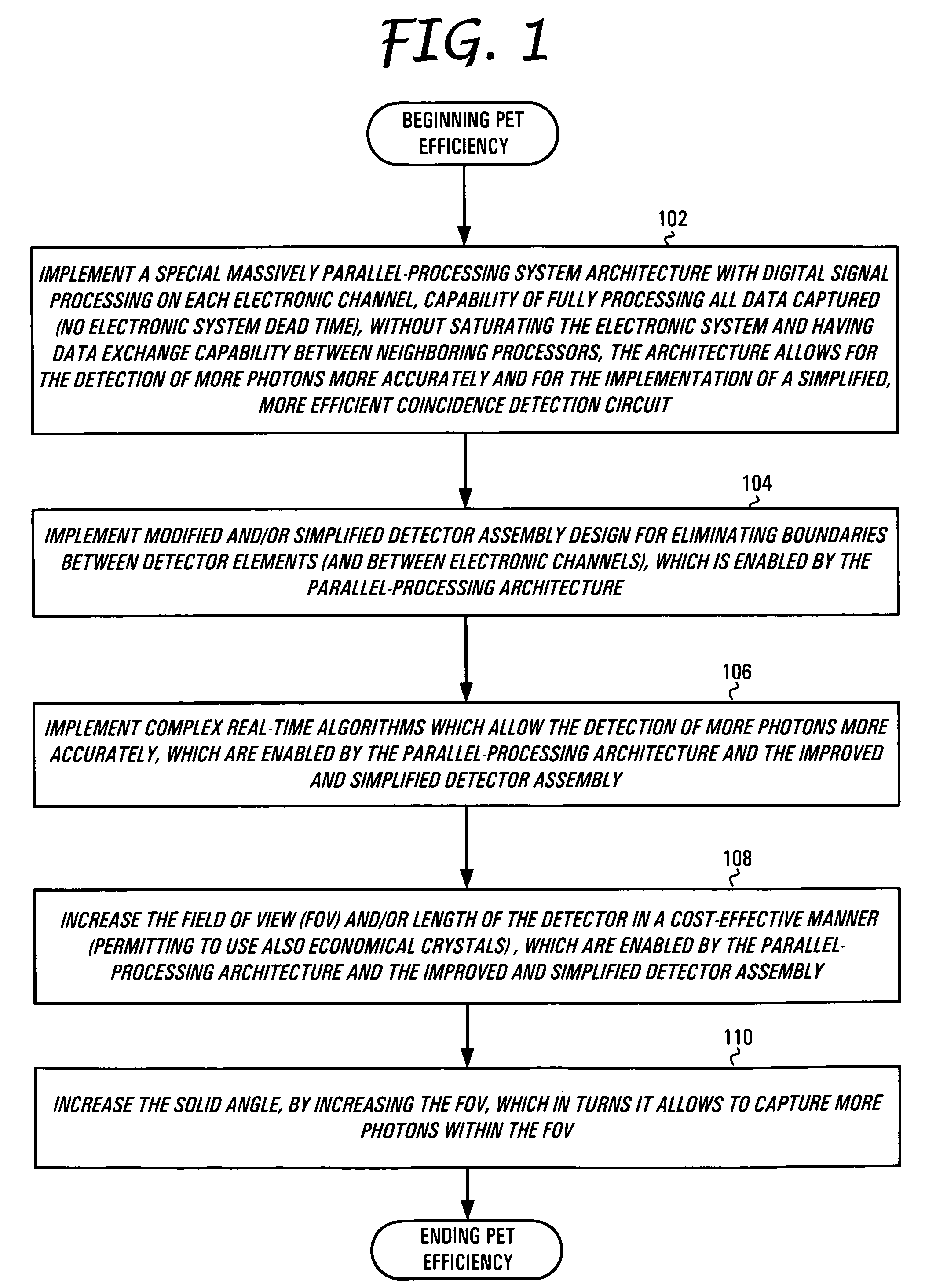
[0019]The present invention is directed to a system, method and software product for increasing the efficiency of a PET device. The present invention is directed to a series of improvements which are concatenated and relates to provide the efficiencies of over 400 times that of prior art PET devices.
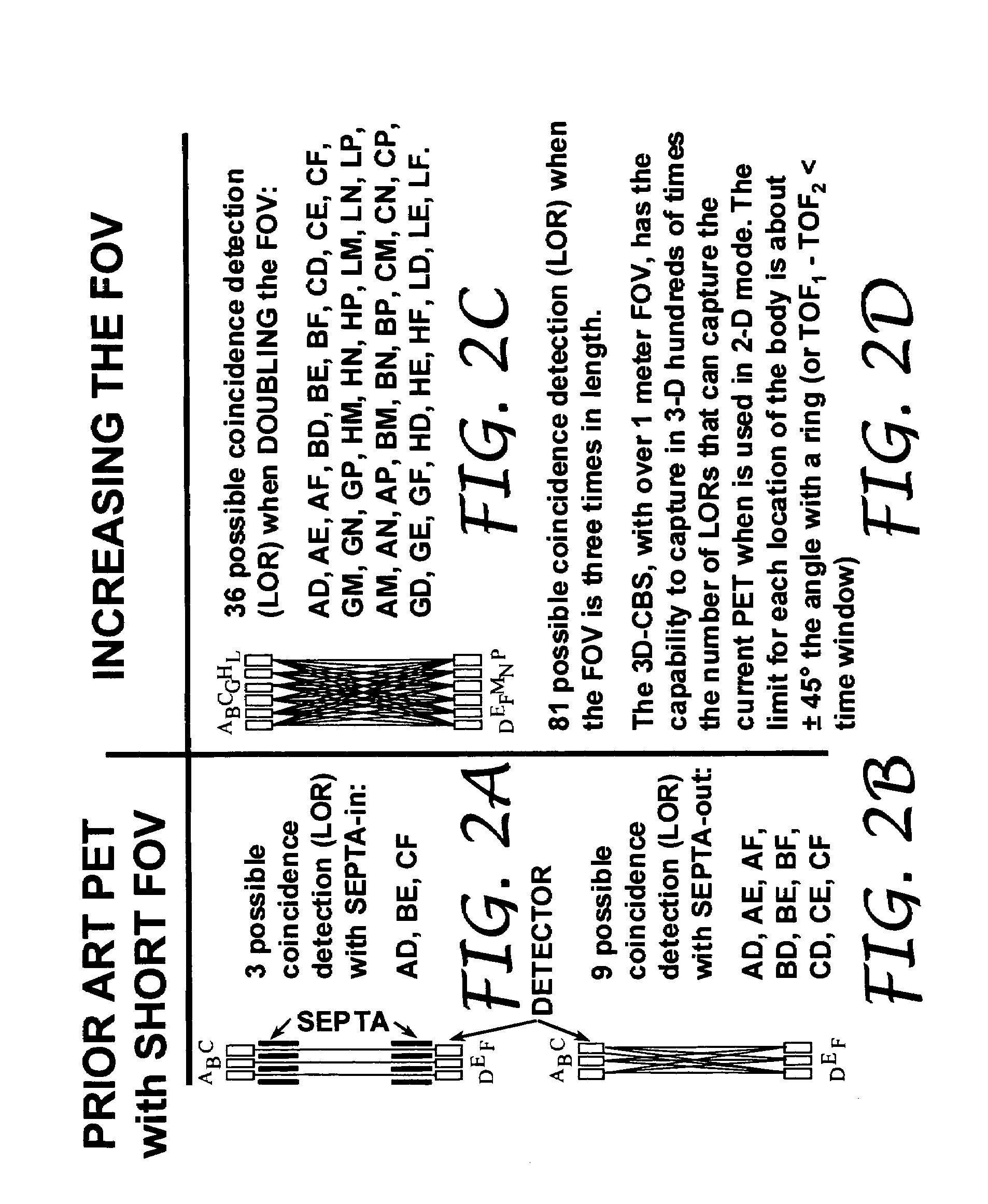
[0020]A modular, digital system, fully programmable and scalable for a multi-modality, open (to accommodate claustrophobic or overweight patients, with the option of closing the detector, to increase efficiency), utilizing both Positron Emission Tomography (PET) and Computed Tomography (CT) in one unit is presented herein for VME and IBM-PC based platforms. The present invention fully exploits the double photon emission occurrence and allows for annual whole-body screening for cancer and other systemic anomalies; only 1 / 30 the radiation dosage; a reduction in scan time to 4 minutes for an axial Field of View (FOV) of 137.4 cm as opposed to 55 minutes for an axial FOV of 16 cm; a decrease in examination cost by 90%; an increase in sensitivity, providing physicians with additional clinical information on a specific organ or area and contribute to the specificity in detecting and assessing cancer.
[0021]The present system collects digital data from multiple electronic channels. Each electronic channel carries the information (64-bit) of all sensors included in a given view angle of the detector. The 64-bits data packets acquired at 20 MHz by each channel with zero dead-time are correlated with neighboring information and processed in real time by a DSP processor to improve the signal-to-noise ratio and extract and measure particle properties, resulting in the identification of the particle's position, accurate energy measurement, Depth of Current PET devices Interaction (DOI), and the timing measurements. A thorough real-time algorithm that best identifies the photons can be executed because the 3D-Flow sequentially-implemented, parallel architecture (SIPA) allows for processing time to be extended in a pipeline stage beyond the time interval between two consecutive input data by configuring by-pass switches in parallel with the processors. Very low power consumption drivers drive short, equal-length PCB traces between 3D-Flow chips, solving the problem of signal skew, ground bounce, cross-talk and noise. The electronics validate and separate events from the different modalities (PET / CT); PET events are checked for coincidences using a circuit sensitive to radiation activity rather than the number of detector elements. Both PET and CT examinations occur at the same time in a stationary bed position using a detector with a long axial FOV, avoiding motion artifacts, increasing throughput, reducing examination cost, reducing radiation to patients, increasing resolution, improving data quality, and reducing erroneous readings (false positives). The saturation of the electronics in prior art PET is overcome by using a system with an input bandwidth of 35 billion events per second distributed over 1,792 channels. The output bandwidth is selectable to sustain the activity generated by the maximum radiation that a PET / CT should ever receive.

Problems solved by technology

While particle detection in high energy physics and medical imaging have some common ground, differences between the disciplines are sticking.
However, although the price and performance of the systems from the different manufacturers are comparable, one manufacturer's system (Siemens) uses nearly ideal crystal detectors, while contrastingly, the other manufacturer's system (General Electric) uses cheaper, lower quality crystal detectors with slower decay time.

Method used


Image

  • Method and apparatus for improving PET detectors
  • Method and apparatus for improving PET detectors
  • Method and apparatus for improving PET detectors

Examples


Embodiment Construction

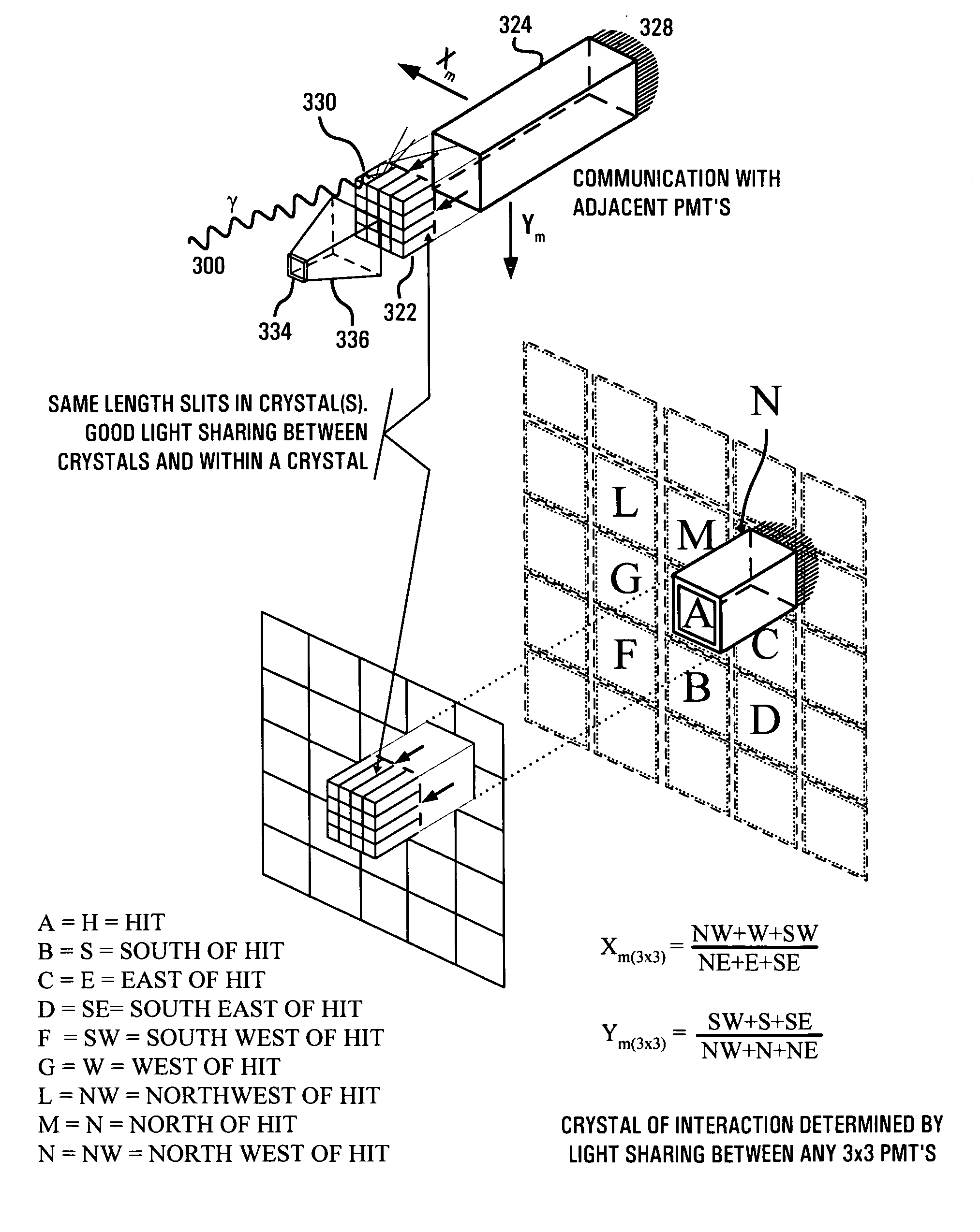
[0044]The present invention, referred to internally herein as the three-dimensional complete body screening (3D-CBS) compared to the current Positron Emission Tomography (PET), encompasses a plurality of inventions disclosed herein and in related patents and co-pending patent applications identified throughout this disclosure. The scope of the corpus of inventions that comprises the 3D-CBS may not be fully appreciated without carefully examining the 3D-CBS from various perspectives which are important for medical professions that engage in human body scanning. Therefore, prior to discussing the exemplary embodiments of the present invention, the differences between the 3D-CBS system of inventions will be discussed with respect to a PET known in the prior art. Here, it should be understood that, although the 3D-CBS system will be discussed with regard to implementation in an exemplary embodiment of a PET, those of ordinary skill in the art will appreciate that the disclosed invention...


PUM


Abstract

The present invention is directed to a system, method and software program product for implementing 3-D Complete-Body-Screening medical imaging which combines the benefits of the functional imaging capability of PET with those of the anatomical imaging capability of CT. The present invention enables execution of more complex algorithms measuring more accurately the information obtained from the collision of a photon with a detector. The present invention overcomes input and coincidence bottlenecks inherent in the prior art by implementing a massively parallel, layered architecture with separate processor stacks for handling each channel. The prior art coincidence bottleneck is overcome by limiting coincidence comparisons to those with a time stamp occurring within a predefined time window. The increased efficiency provides the bandwidth necessary for increasing the throughput even more by extending the FOV to over one meter in length and the execution of even more complex algorithms.

Description

CROSS REFERENCES TO RELATED APPLICATIONS[0001]The present application is related to and claims priority from the co-pending U.S. provisional patent application entitled “METHOD AND APPARATUS FOR IMPROVING PET DETECTORS” having application No. 60 / 424,933 filed on Nov. 9, 2002 and is incorporated by reference herein by reference in its entirety.[0002]The present application is also related to the following patent applications:[0003]U.S. Pat. No. 5,937,202 filed Feb. 15, 1996 entitled “High-Speed, Parallel, Processor Architecture for Front-End Electronics, Based on a Single Type of ASIC, and Method Use Thereof,” (hereinafter U.S. patent '202).[0004]U.S. patent application Ser. No. 09 / 506,207 filed Feb. 15, 2000 entitled “Method and Apparatus for Extending Processing Time in One Pipeline Stage,” (hereinafter U.S. application '207), which claims priority from: U.S. Provisional Patent Application No. 60 / 120,194 filed Feb. 16, 1999; U.S. Provisional Patent Application No. 60 / 112,130 filed ...

Claims


Application Information

Patent Timeline
Patent Type & Authority Patents(United States)
IPC IPC(8): G01T1/202
CPCG01T1/1612G01T1/1615A61B6/037G01T1/2985G01T1/1642
Inventor CROSETTO, DARIO B.
Owner CROSETTO DARIO B
Learn More