Optical recording/reproducing method and optical recording medium

a recording medium and optical recording technology, applied in optical recording/reproducing/erasing methods, mechanical recording, instruments, etc., can solve the problems of difficult to improve the long-term storage reliability of the medium, warpage and tilt of the optical recording medium, and achieve excellent optical recording/reproducing characteristics and simple film structure

Active Publication Date: 2006-11-14
TDK CORPARATION
View PDF4 Cites 25 Cited by
  • Summary
  • Abstract
  • Description
  • Claims
  • Application Information

AI Technical Summary

Benefits of technology

[0016]As a result of an intensive study, the inventor has found that a simple film structure using environmentally friendly materials such as Sn and ZnS can provide excellent optical recording / reproducing characteristics.

Problems solved by technology

Since organic dyes degrade when exposed to sunlight, for example, it is not easy to improve long-term storage reliability of the medium using such an organic dye in the recording layer thereof.
On the other hand, if the NA of the object lens is raised to focus the laser beam, such a problem arises that the tolerance of warpage and tilt of the optical recording medium, namely, the tilt margin becomes very small.
Thus, in the next-generation type optical recording media, different from the currently-used optical recording media such as CD and DVD, it is difficult to form a recording layer and the like on the light transmission layer (transparent substrate).
However, a problem is found that when the recording layer is made of two reaction layers deposited on the substrate in the next-generation optical recording media the noise level is likely to become high (the C / N ratio becomes small) during signal restoration, compared with the conventional optical recording media such as CD and DVD where the recording layer formed in the light transmission layer (transparent substrate) is made of two reaction layers.

Method used


Image

  • Optical recording/reproducing method and optical recording medium
  • Optical recording/reproducing method and optical recording medium
  • Optical recording/reproducing method and optical recording medium

Examples


examples and compared examples

[0080]Now the present invention will be explained more specifically along with some examples, but the invention is not limited to those examples.

[Preparation of the optical recording medium]

example 1

[0081]Optical recording media were fabricated via the following steps.

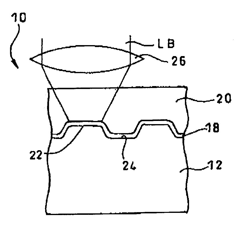
[0082]First, a polycarbonate substrate of which thickness was 1.1 mm and diameter was 120 mm was set in a sputtering apparatus. On the light reflection layer of this polycarbonate substrate, a recording layer having a thickness of 10 nm was formed by simultaneously sputtering the dielectric material made of a mixture of ZnS and SiO2 and the recording assist material made of Sn. It was designed to have the recording assist material and ZnS—SiO2 (80:20) at a molar ratio of 50:50.

[0083]Next, on the recording layer, an acrylic ultraviolet-curable resin was coated by the spin coating method and the light transmission layer (thickness: 100 μm) was formed by ultraviolet irradiation thereon.

[0084]The molar ratio between ZnS and Sio2 in the first and second dielectric layers was ZnS:SiO2=80:20 .

examples 2 and 3

[0085]Examples 2 and 3 were prepared in the same manner as in the example 1 except that Sn in the example 1 was replaced by Ag and Ti, respectively.

Compared Example

[0086]In the compared example, an optical recording medium was fabricated to have a single-layered structure where the recording layer was made of only Sn.

Example(s) 4–12

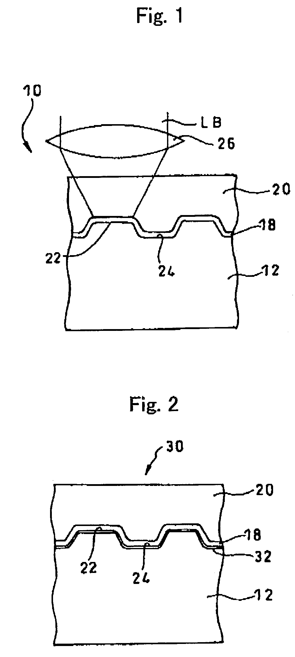
[0087]The optical recording medium with a recording layer of a single-layer structure was fabricated without forming any dielectric layer. The recording layer was made of a mixture of ZnS—SiO2 (ZnS:SiO2=80:20) and a metal or semi-metal of Mg, Nb, Bi, Mg, Au, Al, Au, Cu, Ta, or Si.

Example(s) 13–34

[0088]The optical recording media were fabricated by replacing ZnS—SiOz (ZnS:SiO2=80:20) employed in the examples 4–12 to other materials. Mg (examples 13–17), Ti (examples 18–25), Sn (examples 26,27), Nb (examples 28–30), or Al (examples 31–34) was mixed in the optical recording medium.

Example(s) 35–37

[0089]The optical recording medium with a recording layer of a...


PUM

PropertyMeasurementUnit
wavelengthaaaaaaaaaa
thickaaaaaaaaaa

Abstract

An optical recording / reproducing method and an optical recording medium capable of performing excellent optical recording with a simple structure in a recording layer made of environmentally friendly materials. The optical recording medium has a recording layer formed on a substrate and made of a mixture of a recording assist material and a dielectric material. A laser beam of which intensity is modulated in accordance with information to be recorded is irradiated onto this recording layer to cause a state change in the recording assist material and / or the dielectric material. The information can be recorded by changing optical characteristics thereof such as reflectivity. The recording assist material includes an element selected from Sn, Ti, Si, Bi, Ge, and C as a principle component, while the dielectric material as a base material for the dielectric layers is at least one of ZnS, SiO2, AlN, and Ta2O5.

Description

BACKGROUND OF THE INVENTION[0001]1. Field of the Invention[0002]The present invention relates to an optical recording medium and an optical recording / reproducing method using the same.[0003]2. Related Art[0004]As recording media for recording digital data, optical recording media such as CD (Compact Disc) and DVD (Digital Versatile Disc) have been widely used. These optical recording media can be broadly classified into the ROM-type optical recording media such as CD-ROM (Read Only Memory) and DVD-ROM where data is not added or rewritable, the write-once type optical recording media such as CD-R (Recordable) and DVD-R where data can be added but not rewritable, and the rewritable optical recording media such as CD-RW (Rewritable) and DVD-RW where data is rewritable.[0005]As well known, in the ROM-type optical recording media, data is usually recorded in the form of pre-pits formed on the substrate during manufacturing. In the rewritable optical recording media, phase-change material...

Claims


Application Information

Patent Timeline
Patent Type & Authority Patents(United States)
IPC IPC(8): G11B7/00G11B7/004G11B7/0045G11B7/243G11B7/256G11B7/257
CPCG11B7/00455G11B7/243G11B7/257G11B2007/24314G11B2007/24328G11B7/002
Inventor INOUE, HIROYASUMISHIMA, KOJIAOSHIMA, MASAKIHIRATA, HIDEKIUTSUNOMIYA, HAJIMEARAI, HITOSHITANAKA, YOSHITOMO
Owner TDK CORPARATION
Why Eureka
Try Eureka