Level conversion circuit and serial/parallel conversion circuit with level conversion function

a level conversion circuit and level conversion function technology, applied in logic circuit coupling/interface arrangement, pulse technique, instruments, etc., can solve the problems of insufficient high-speed operation, inferior crystal quality of low-temperature polysilicon tft, and inability to reduce the occupied area, etc., to achieve low power consumption and high speed

Inactive Publication Date: 2006-11-21
MITSUBISHI ELECTRIC CORP
View PDF7 Cites 27 Cited by
  • Summary
  • Abstract
  • Description
  • Claims
  • Application Information

AI Technical Summary

Benefits of technology

[0015]An object of the present invention is to provide a level conversion circuit capable of converting a signal of small voltage amplitude into a signal of large voltage amplitude at a high speed and with low power consumption as well as a serial / parallel level conversion circuit using the level conversion circuit.
[0031]According to the first aspect of the invention, the input signal is held in the MOS capacitance element. Accordingly, when the input signal is sampled, the MOS capacitance element stops the operation as the capacitance element, to cause the voltage held in the MOS capacitance element to change according to the input signal at a high speed. A high-speed level conversion is thus achieved. Further, according to the charged voltage of the MOS capacitance element, the clocked inverter is driven. Then, the clocked inverter can be driven for only a required period of time to reduce current consumption. Moreover, by applying the clock signal on the second clock input node to the MOS capacitance element, the voltage held therein can be boosted through a charge pump operation. It is thus ensured to drive a clocked inverter at a subsequent stage. The period of time in which through current flows in the clocked inverter can be shortened and accordingly current consumption can be reduced.
[0032]According to the second aspect of the invention, the input signal is sampled, the second clock signal is transferred to the clocked inverter at the subsequent stage according to the sampled voltage, and the clocked inverter at the subsequent stage drives the internal node according to the transferred signal. With the second clock signal, the second MOS transistor can be operated as a MOS capacitance element so that the gate potential thereof is increased to rapidly change the potential on the internal output node.
[0033]According to the third aspect of the invention, similarly to the first aspect of the invention, the input signal is held at the MOS capacitor and the input signal is boosted through charge pump operation of the MOS capacitor. Thus, the input signal can be sampled and level-converted at high speed. In addition, control of conduction / non-conduction of the first insulated gate field effect transistor and the control of charge pump operation by MOS capacitor can be made by separate clock signals, the timing for sampling the input signal can be optimized and thus, level-conversion can be performed accurately with reduced current consumption.
[0034]According to the fourth aspect of the invention, the input signal is sampled according to complementary clock signals and the clock signal is transferred to an input of the clocked inverter in accordance with the taken-in input signal. The clocked inverter is activated in parallel with the clock signal transfer and thus, the input signal can be converted into a signal having an amplitude the same as the clock signal. The input signal merely drives the gate of the insulated gate field effect transistor and the load thereof is very small. As a result, the input signal can be taken in and level-converted at high speed.
[0040]According to the tenth aspect of the invention, a plurality of level conversion circuits of the second aspect are provided and the level conversoin circuits perform the sampling operations at different timings from each other in accordance with the sampling clock signals. Further, after the sampling operation by the level conversion circuit at the preceding stage is completed, the sampling operation by the level conversion circuit at the subsequent stage is carried out. Thus, input signals applied serially can accurately be level-converted to generate parallel signals. Moreover, only a selected level conversoin circuit is coupled to the input signal so that the load of the input signal is reduced and accordingly current consumption can be reduced.

Problems solved by technology

Thus, as compared with a MOS transistor using single-crystal silicon, the crystal quality of the low-temperature polysilicon TFT is inferior.
Therefore, the current drivability of the output drive transistor is small, and a level-converted signal of a large amplitude that is held in the second capacitance element cannot be discharged at a high speed, resulting in a problem that a high-speed operation is not ensured.
Accordingly, the input buffer circuit has a large number of transistor elements, resulting in a problem that the occupied area cannot be reduced.
In addition, if the transistor elements have greatly-varied threshold voltages, offset in a comparison stage of the current-mirror type input buffer circuit cannot be compensated for, resulting in a problem that an accurate input signal cannot be generated.
Accordingly, in the output drive stage, both of charging and discharging drive transistors are in an ON state, resulting in a problem that a through current flows all the time.
Accordingly, it is required to provide capacitance elements respectively for the high-side drive transistor and the low-side transistor on the node receiving the input signal, resulting in a problem that the load of the input signal increases.
Thus, if a skew occurs between the complementary input signals, the signal on the internal output node is coupled via the second drive transistor to the input signal, resulting in a problem that the internal output node cannot sufficiently charged and thus an accurately level-converted signal cannot be generated.

Method used


Image

  • Level conversion circuit and serial/parallel conversion circuit with level conversion function
  • Level conversion circuit and serial/parallel conversion circuit with level conversion function
  • Level conversion circuit and serial/parallel conversion circuit with level conversion function

Examples


first embodiment

[0069

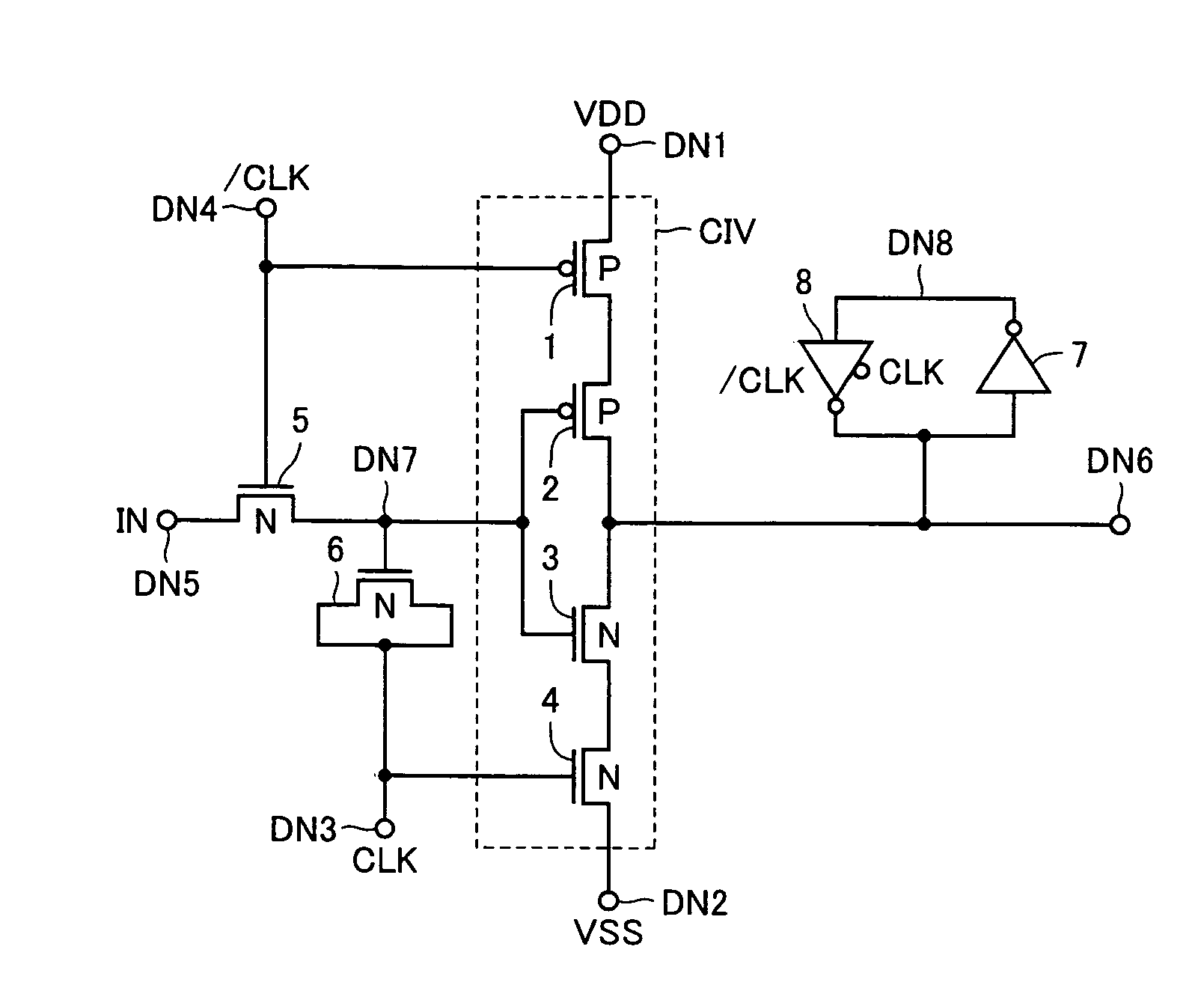
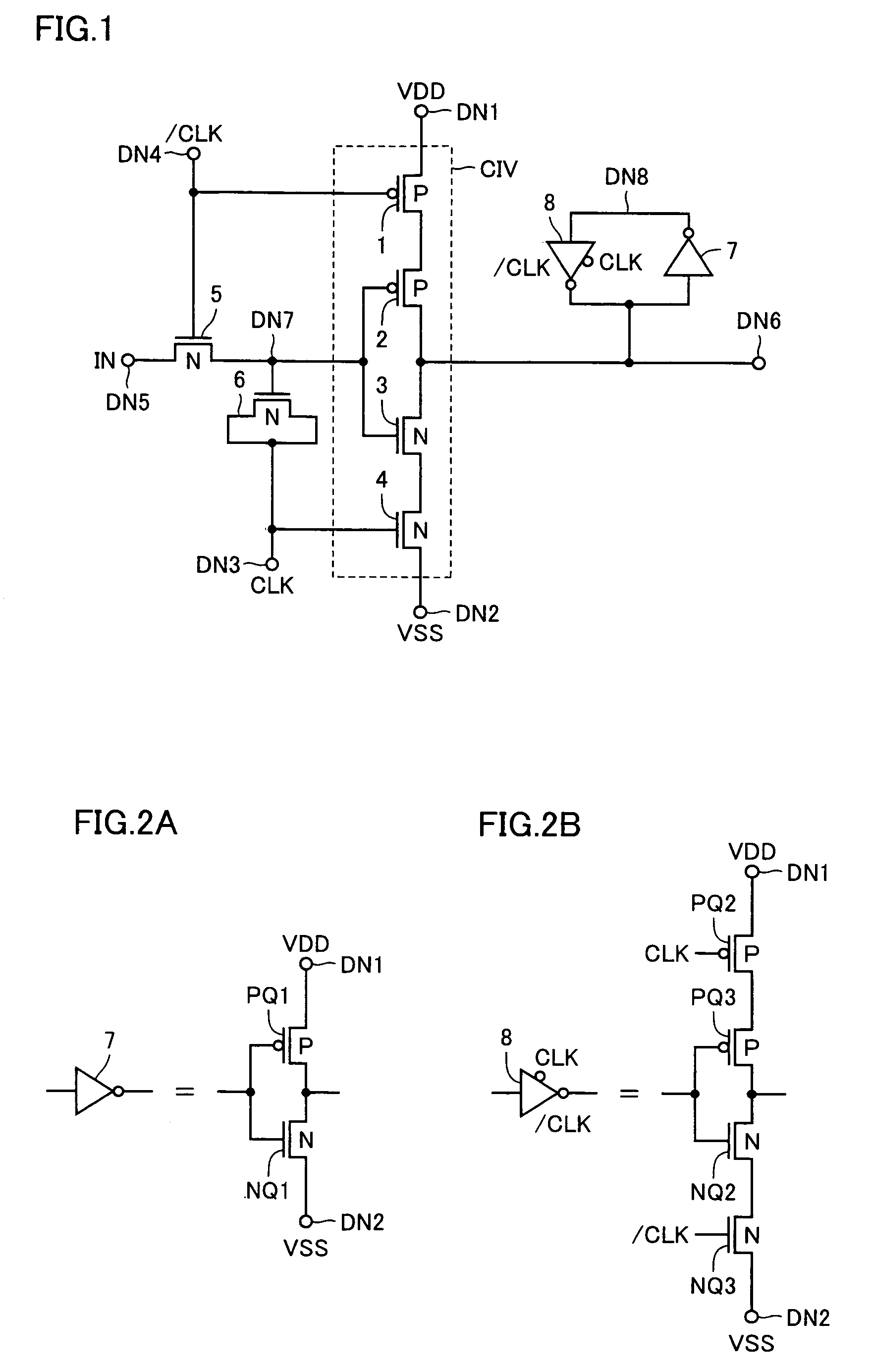
[0070]FIG. 1 shows a configuration of a level conversion circuit according to a first embodiment of the present invention. Referring to FIG. 1, the level conversion circuit includes an N-channel MOS transistor (insulated gate field effect transistor) 5 transmitting an input signal IN applied to an input node DN5 to an internal node DN7 according to a clock signal / CLK applied to an input node DN4, a MOS-type capacitance element (hereinafter referred to as MOS capacitor) 6 coupled to internal node DN7 and selectively forming a capacitor according to a clock signal CLK from a clock input node DN3, a clocked inverter CIV selectively activated according to clock signals CLK and / CLK and driving, when activated, an internal output node DN6 according to the signal on internal node DN7, and an inverter 7 and a clocked inverter 8 that constitute a latch circuit latching a signal voltage on internal output node DN6.

[0071]When this level conversion circuit is used in a display device (di...

second embodiment

[0096

[0097]FIG. 4 shows a configuration of a level conversion circuit according to a second embodiment of the present invention. The configuration of the level conversion circuit shown in FIG. 4 differs from that of the level conversion circuit shown in FIG. 1 in that, to low-side power supply node DN2 of clocked inverter CIV, clock signal / CLK is applied instead of the measurement reference voltage (ground voltage VSS). Other configuration of the level conversion circuit shown in FIG. 4 is identical to that of the level conversion circuit shown in FIG. 1. Therefore, like components are denoted by like reference numerals and the detailed description thereof is not repeated.

[0098]In the level conversion circuit shown in FIG. 4, clock signal CLK changes with a delay to clock signal / CLK.

[0099]FIG. 5 is a signal waveform diagram representing an operation of the level conversion circuit shown in FIG. 4 in the case where the clock skew large. As shown in FIG. 5, it is assumed now that in...

third embodiment

[0117

[0118]FIG. 8 shows a configuration of a level conversion circuit according to a third embodiment of the present invention. The configuration of the level conversion circuit shown in FIG. 8 differs from that of the level conversion circuit shown in FIG. 1 or 4 in that, the gate of P-channel MOS transistor 1 of clocked inverter CIV that is connected to high-side power supply node DN1 is connected to internal node DN7 and clock signal / CLK is applied to the gate of P-channel MOS transistor 2 connected to internal output node DN6. Similarly, clock signal CLK is applied to the gate of N-channel MOS transistor 3 and the gate of N-channel MOS transistor 4 connected to low-side power supply node DN2 is connected to internal node DN7. Further, to low-side power-supply node DN2, reference voltage VSS or clock signal / CLK is applied. Other configuration of the level conversion circuit shown in FIG. 8 is identical to the level conversion circuit shown in FIG. 1 or 4. Therefore, like compon...


PUM


Abstract

A MOS capacitor receiving a clock signal complementary to a sampling clock signal is provided at an input of a clocked inverter that is activated after sampling an input signal to perform level conversion. A charge pump operation of the MOS capacitor is performed in parallel with the activation of the clocked inverter. The power consumption of and the area occupied by a level conversion circuit converting a voltage amplitude of the input signal are reduced without deteriorating a high-speed operating characteristics.

Description

BACKGROUND OF THE INVENTION[0001]1. Field of the Invention[0002]The present invention relates to a level conversion circuit using insulated gate field effect transistors (MOS transistors). In particular, the present invention relates to a level shift circuit having a latch function and used for display devices formed using, for example, liquid-crystal elements or organic electroluminescence (EL) elements. More specifically, the present invention relates to a circuit configuration for latching and level-shifting a pixel data signal applied to a display pixel.[0003]2. Description of the Background Art[0004]In a display device using liquid-crystal elements or organic EL (electroluminescence) elements as display pixel elements, a level conversion circuit is employed for enlarging a signal amplitude. For example, in order to accurately drive the display pixel elements in accordance with a display signal, for achieving gradational display, the amplitude of an image data signal is enlarged...

Claims


Application Information

Patent Timeline
Patent Type & Authority Patents(United States)
IPC IPC(8): H03K19/0175G09G3/20H03K19/0185G11C19/18G11C27/02H03L7/06H03M9/00
CPCG09G3/20H03M9/00H03K19/01855G09G2310/027G09G2310/0294G09G2310/0289H05B3/20H05B3/10H05B2203/016H05B2203/019H05B2203/02H05B2203/021
Inventor TOBITA, YOUICHI
Owner MITSUBISHI ELECTRIC CORP
Why Eureka
Try Eureka